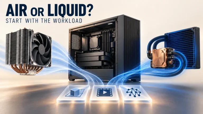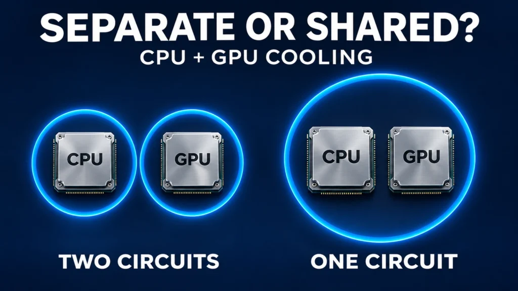
Choose separate CPU and GPU circuits when independent thermal control, service isolation or different operating requirements justify the extra hardware. Consider a shared circuit when the devices can use compatible fluid conditions and the complete loop can meet concurrent-load, noise and service targets within the chassis. Neither layout is automatically cooler or more reliable.
The important comparison is between two complete configurations. A shared loop with adequate heat rejection should not be compared with two undersized radiators, and two independent loops should not be credited with fault tolerance that the workstation controls cannot deliver.
Define what is separate before comparing performance
Here, a separate-loop architecture means the CPU and liquid-cooled GPU have hydraulically independent coolant circuits. Each needs an identified circulation and heat-rejection path. A shared loop connects both device cooling paths to a common coolant circuit; it can contain serial blocks or parallel branches. Two branches in one loop are not two independent loops.
A CPU liquid cooler with an air-cooled GPU is a third configuration. It may be suitable, but the GPU’s heat still enters the chassis air path. Do not describe it as a dual liquid loop. Likewise, sharing a fan wall, intake or controller can couple two otherwise independent circuits through air temperature or control behavior.
ThermalBro’s workstation module range provides CPU-platform module examples. Adding a GPU is a project-specific integration question, including the exact board, contact surfaces and service boundary; a CPU module listing is not evidence of universal GPU compatibility.
Compare the workloads that actually overlap
Build the workload matrix around three cases:
- CPU-dominant work. Record the real job, intended performance state and sustained duration.
- GPU-dominant work. Record GPU activity, CPU background activity and the relevant device limits.
- Concurrent work. Identify applications that load both together and the conditions after radiator and chassis air have warmed.
For each case, record ambient/inlet conditions, device temperatures and completed work. Separate single-device benchmarks cannot establish the shared circuit’s combined-load result.
In a shared circuit, heat from both devices reaches a common coolant system. Under GPU-heavy work, radiator capacity that would otherwise be assigned exclusively to a lightly loaded CPU may contribute to heat rejection. That benefit depends on the actual radiator, airflow and coolant operating conditions; it is not free capacity created by connecting hoses.
Separate circuits give each device an assigned cooling path. This can help when one device needs tighter temperature control or must be changed independently. It can also leave one radiator lightly used while the other is constrained. Compare the combined workload rather than summing two unrelated single-device test results.
Compare complete cooling configurations
Swipe the table horizontally to compare all columns.
| Decision input | Shared circuit | Separate circuits |
|---|---|---|
| Alternating CPU and GPU load | Common heat-rejection hardware may serve either load | Capacity remains assigned to each circuit |
| Sustained concurrent load | Validate combined heat and each device temperature | Validate both loops and shared chassis air conditions |
| Different coolant requirements | Common fluid must be compatible with every wetted component | Independent fluids may be possible with controlled service procedures |
| GPU replacement | May require disturbing the CPU cooling circuit | Hydraulic separation can reduce the affected service scope |
| Chassis space | May reduce duplicated circulation hardware | Additional pumps, tubing and mounting space must fit |
Check flow distribution and temperature together
For serial blocks, the same circuit flow passes through the CPU and GPU cooling paths. Their restrictions, hoses, connectors and radiator contribute to the total pressure loss. Select the pump from the intersection of its available pressure-flow curve and the actual circuit resistance at the relevant fluid conditions. A maximum free-flow number does not describe this operating point.
In parallel branches, total pump flow divides according to branch resistance. Equal-looking hoses do not establish equal flow, and equal flow is not necessarily the correct target for different cold plates. Check the required flow in each branch, its pressure loss and the behavior when a branch is changed or restricted. A total-loop flow reading can hide an under-supplied branch.
Coolant warms as it collects heat. The resulting temperature difference depends on heat entering the fluid, mass flow and fluid properties. It does not directly equal the difference in CPU or GPU junction temperature: contact quality, heat distribution and cold-plate behavior also matter. Review each device against its own temperature limit and actual inlet conditions.
Avoid choosing the architecture solely to put the CPU “first.” A convenient route with suitable flow, filling and service access can be more useful than a complicated route intended to eliminate a small unquantified coolant temperature difference. If order matters to the project’s margin, measure or model that configuration rather than assuming a universal result.
From inputs to a defensible decision
CPU-only, GPU-only and concurrent cases
↓ Define the required performance and temperature limits.
Serial path, parallel branches or independent loops
↓ Verify device flow and inlet conditions.
Chassis air, control and service
↓ Validate the installed configuration.
Treat radiator placement and noise as system decisions
Two liquid circuits can still heat each other’s intake air. If one radiator exhausts into another radiator’s intake, the downstream unit operates with warmer air. Case filters, panel restrictions, cable placement and other heat sources also affect the available airflow. Record radiator inlet air temperatures in the installed chassis, not just room temperature.
Separate loops do not guarantee lower noise. Additional pumps can add vibration or tonal noise, while a shared loop may require a different pump operating point. Fan demand depends on heat rejection and airflow resistance. Compare acoustic behavior at the same useful workload and thermal limits, with a stated measurement position and background condition.
The workstation cooling integration guide explains the broader chassis and interface inputs. For this decision, use those inputs to test whether the proposed radiators, hoses, pumps and access paths can coexist with the exact motherboard and GPU layout.
Evaluate maintenance and failure without assuming redundancy
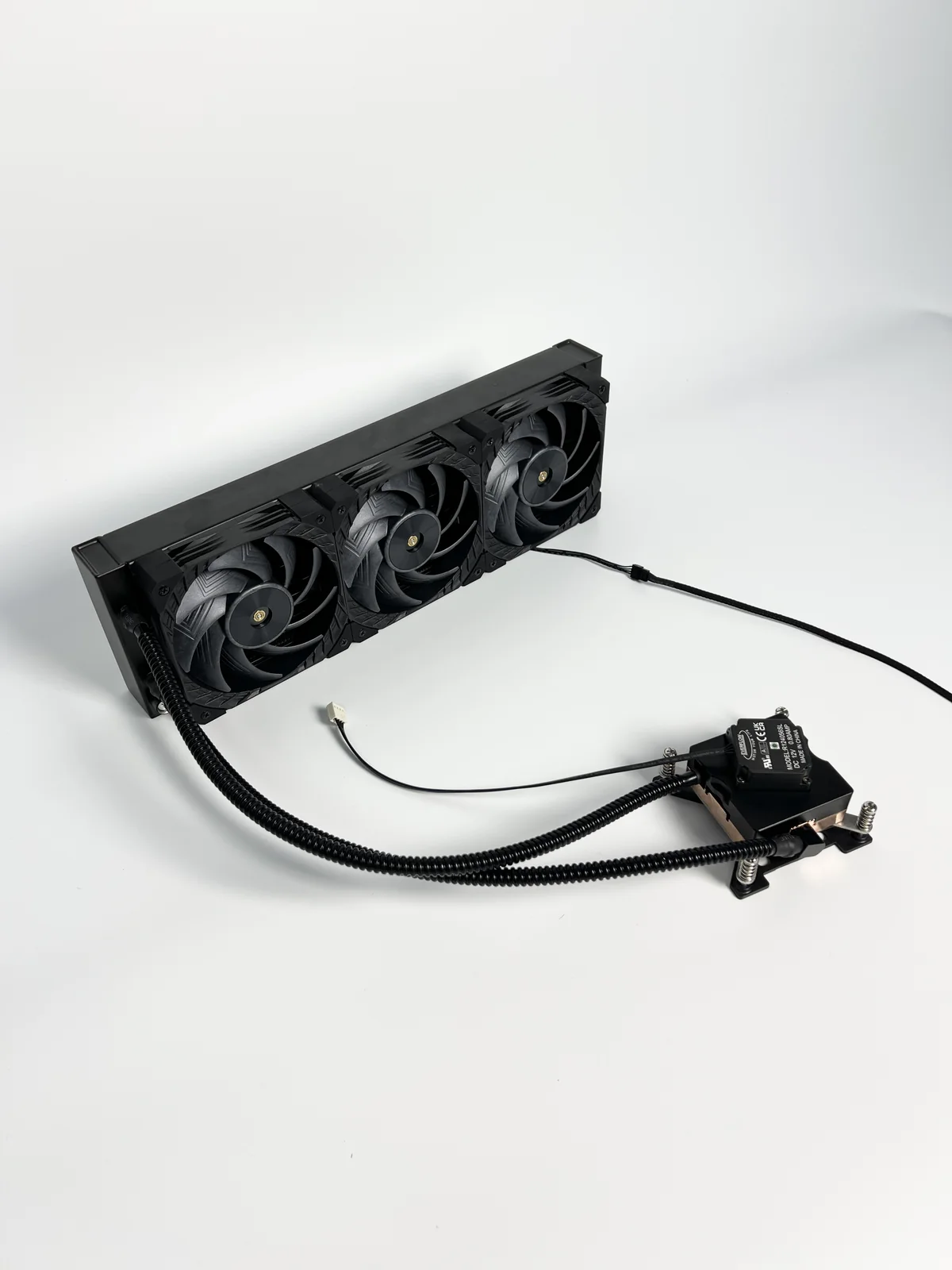
A shared circuit can make one pump or coolant fault relevant to both devices. Separate circuits can confine some hydraulic faults, but the workstation may still need to shut down if the affected device is essential, leakage threatens electronics or the controller cannot safely isolate the fault. Two pumps in different loops are not redundant pumps for either loop.
Compare the same maintenance task for both layouts:
- Define isolation. Identify connections that open, the approved draining or fluid-containment procedure and components that must stop.
- Perform the replacement sequence. Check physical access, disturbed CPU/GPU interfaces, tools and the actual replaceable unit.
- Restore the configuration. Identify required reconnection, leak/functional checks and restart approval; then repeat the review for pump replacement.
Count actual actions and affected interfaces. Hydraulic separation has value only if it simplifies the permitted service sequence or fault response; extra components may still add work.
Specify fault detection and response: loss of flow, unexpected coolant or device temperature, fan failure and leak indication where provided. State who controls shutdown or power limiting and who verifies recovery. Architecture alone does not supply these protections.
Use a fair comparison to make the selection
Consider a hypothetical workstation that mostly runs GPU rendering but also performs long CPU simulations. A shared loop is worth evaluating because the two loads may peak at different times. Before selecting it, the integrator must identify any combined workloads, check GPU branch or serial-flow requirements and confirm the service cost of opening the common circuit.
Shared circuit remains a candidate
Alternating loads and compatible conditions make shared capacity worth evaluating. Confirm concurrent-load behavior, flow distribution and acceptable common-loop service disruption.
Separate circuits gain priority
Frequent GPU exchange without disturbing CPU cooling makes service isolation valuable, provided dedicated heat rejection fits and meets the GPU load and noise limits.
If the dedicated GPU radiator cannot meet its duty within the enclosure, separation is not yet a viable choice. Revisit radiator placement, service interfaces or the enclosure before declaring a winner.
Record a comparable installed-system test
Swipe the table horizontally to compare all columns.
| Comparison record | Keep consistent | Record separately for each layout |
|---|---|---|
| Platform and workload | Board revisions, power settings and application run | Any throttling or performance difference |
| Environment | Room conditions and chassis configuration | Radiator intake and coolant temperatures |
| Hydraulic behavior | Actual coolant specification | Operating flow, branch flow where needed and pump state |
| Thermal result | Device limits and measurement definitions | CPU/GPU temperatures over the defined run |
| Service and noise | Same service task and acoustic method | Steps, disturbed interfaces and measured sound |
Select a candidate only when its unresolved inputs have owners and a validation plan. ThermalBro can review the agreed module and mechanical scope through OEM/ODM engineering; complete-workstation acceptance remains a defined integration task. Use testing and reliability requirements to agree what the sample must demonstrate.
Questions before freezing the circuit layout
Is a shared loop always cheaper?
It may avoid duplicated components, but custom routing, branch control, installation and service requirements can offset that saving. Compare the same supply and testing scope, including what the integrator must add.
Can different CPU and GPU temperatures justify separate loops?
Possibly, if their allowable inlet conditions or control requirements cannot be met appropriately in one circuit. Different observed junction temperatures alone do not establish that need; they also reflect device and contact characteristics.
What should be sent for an architecture review?
Provide exact CPU/GPU and PCB revisions, concurrent workloads, available drawings, chassis airflow, temperature and noise targets, planned maintenance and the intended supply boundary. Mark missing measurements explicitly so the initial recommendation remains traceable to its assumptions.