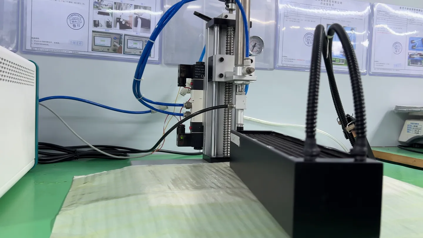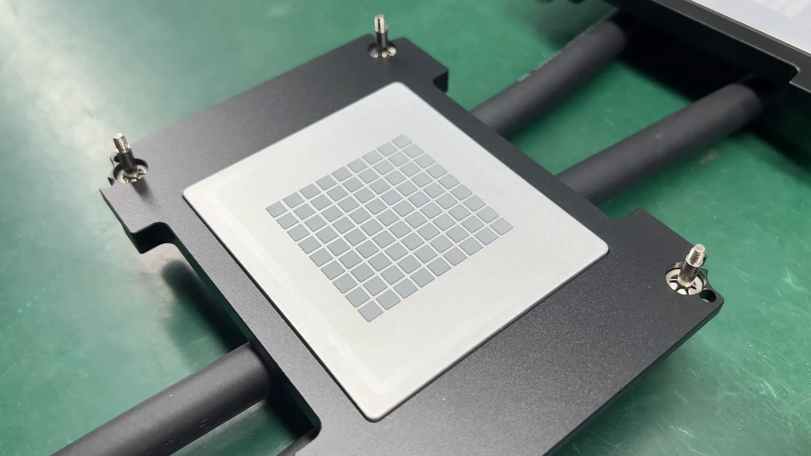
Heat Source
CPU, GPU or other selected device.
Direct-to-chip cooling transfers heat from selected processors to circulating coolant through cold plates. A pump moves the coolant, and a radiator or external heat exchanger removes the heat. Performance depends on the complete loop, operating conditions and controls.
View the System Diagram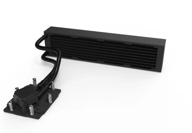
Follow the heat from the processor to the cold plate, through the coolant loop and out to air or facility water. The diagram shows the main functions; component arrangement depends on the system.
CPU, GPU or other selected device.
Interface, flow path and sealing.
Routing, bend, connection and service.
Moves coolant against resistance from the complete loop.
Radiator or external cooling interface.
Sensors and controls for temperature, flow and fault response.
A useful feasibility review starts with controlled platform data and the real system conditions. Values copied from another server configuration do not establish compatibility.
Processor revision, sustained/peak/concurrent workload, permitted temperatures, ambient and inlet conditions.
Socket or PCB, mounting load, chassis height, keep-outs, tube path, assembly and maintenance sequence.
Coolant/material compatibility, inlet range, flow and pressure budget, connections, pump and heat-rejection owner.
Multi-source loops can be arranged in series, parallel or a controlled combination. The choice affects temperature rise, branch balance, pump operating point, tube routing and fault behavior.
| Architecture | Potential benefit | Review before selection |
|---|---|---|
| Series path | Simple routing and one continuous flow path | Downstream coolant temperature and total pressure drop |
| Parallel branches | Separate flow paths for multiple sources | Branch resistance, balancing and low-flow detection |
| Hybrid distribution | Adapts to dense or mixed heat-source layouts | More interfaces, control logic and service complexity |
Specific pressure-drop and flow results must use the defined coolant, temperature, connections and module configuration together with the pump curve.
Plan how to prevent, detect and respond to each risk. Factory checks verify the module, while server and external-system tests assess the installed configuration.
| Risk | Control and evidence |
|---|---|
| Leakage | Seal/connection design, controlled assembly and defined leak-test method |
| Condensation | Coolant temperature, ambient humidity, dew-point margin and operating control |
| Low flow | Loop design, monitoring input, threshold owner and system response |
| Service error | Connection identification, installation sequence and maintenance instruction |
Confirm these items before building a prototype so the hardware and tests reflect the server you intend to use.
For the wider module-to-rack boundary, continue with the Server Liquid Cooling Guide.
No. Direct-to-chip cooling brings a liquid-cooled contact module to selected processors while the rest of the server remains in a conventional chassis. Immersion cooling places equipment in a dielectric fluid and uses a different architecture and service model.
ThermalBro’s documented core scope is liquid cooling modules and related engineering and manufacturing. Rack distribution, CDU and facility-water equipment are separate responsibilities unless a specific written project scope states otherwise.
Pressure drop is evaluated for the defined coolant, temperature, flow range, module and connection configuration. A complete loop review combines component curves with the pump operating point and branch distribution.
Module tests address agreed fit, sealing, flow function and thermal evidence. Server tests add real workloads, airflow, controls, service access and abnormal operation. External distribution and facility interfaces are validated by the responsible system teams.
Method sources: Open Compute Project Cold Plate Cooling and OCP cold-plate loop requirements. External sources describe methods, not ThermalBro product certification.
Share heat-source and chassis files, coolant connections and test requirements. Tell us which pump and heat-rejection equipment will be used.