
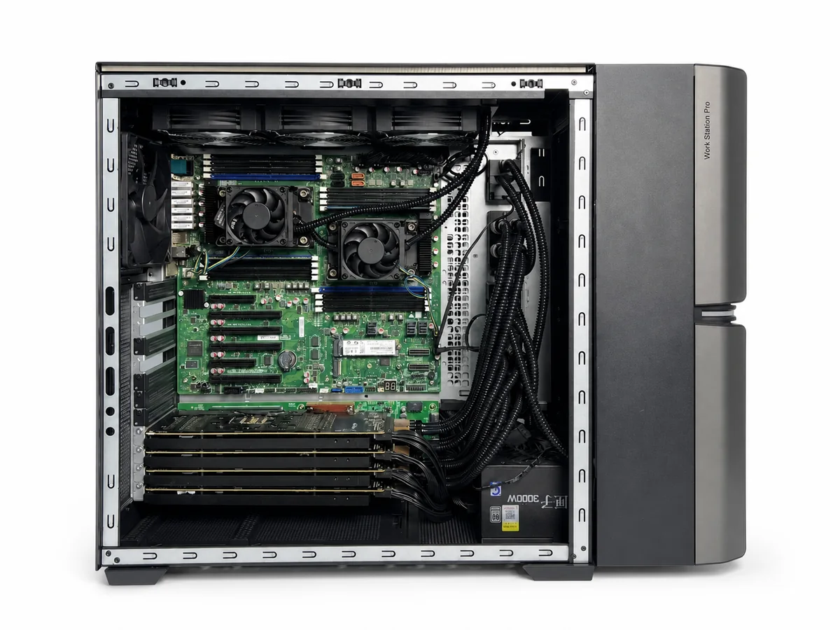
Board and chassis
Mounting points, keep-outs, component heights, orientation and service access.
We develop cooling modules around your server, GPU board or workstation. Our engineering work connects the heat-source layout with cold-plate contact, mounting, tube routing and manufacturing requirements so the design can move into prototyping.
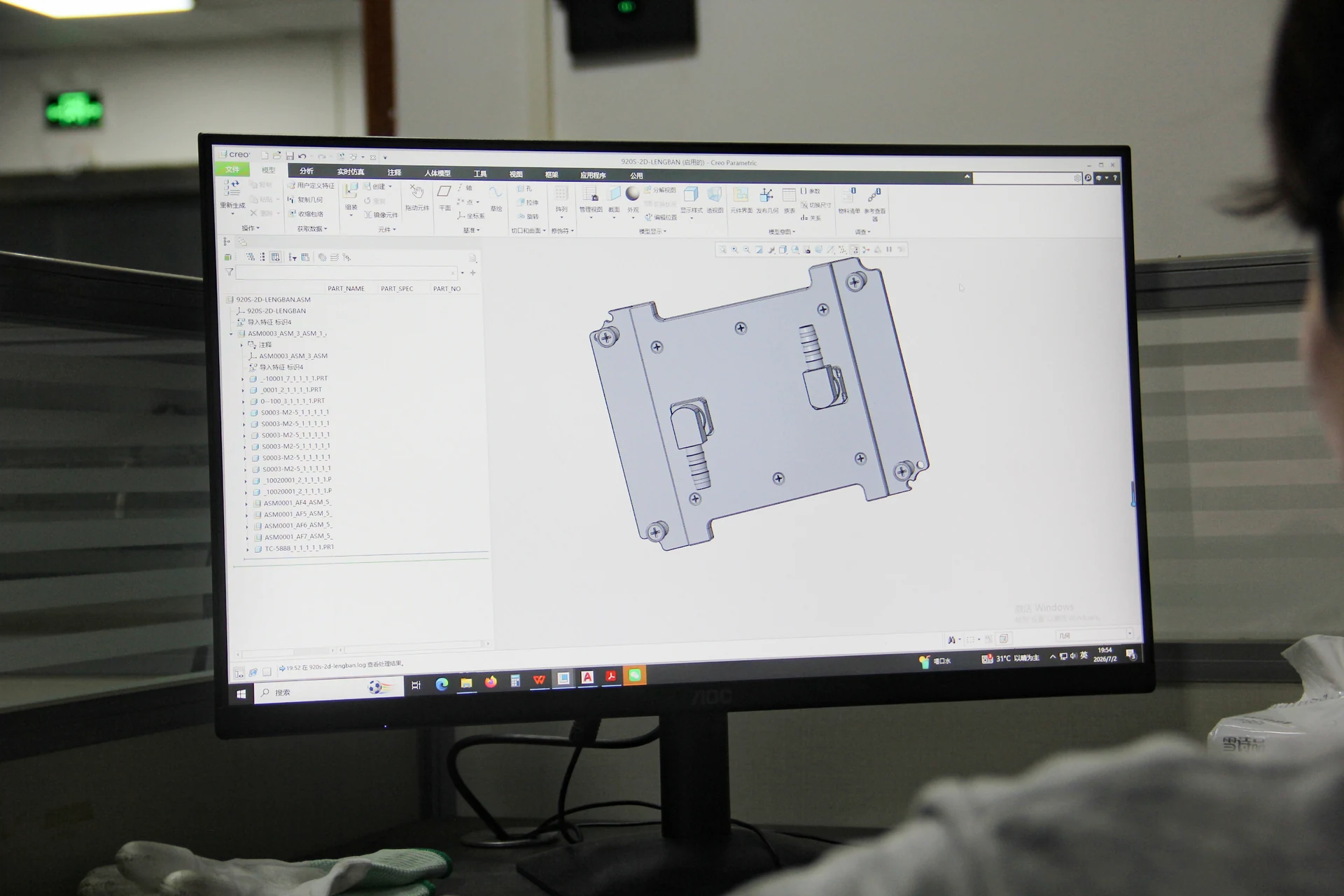
Before selecting components, ThermalBro reviews how heat leaves the device, where the module can fit and how it will be installed and serviced.
Mounting points, keep-outs, component heights, orientation and service access.
Heat-source locations, sustained load, contact surfaces and thermal interface materials.
Flow direction, tube length, connectors and customer-side loop information.
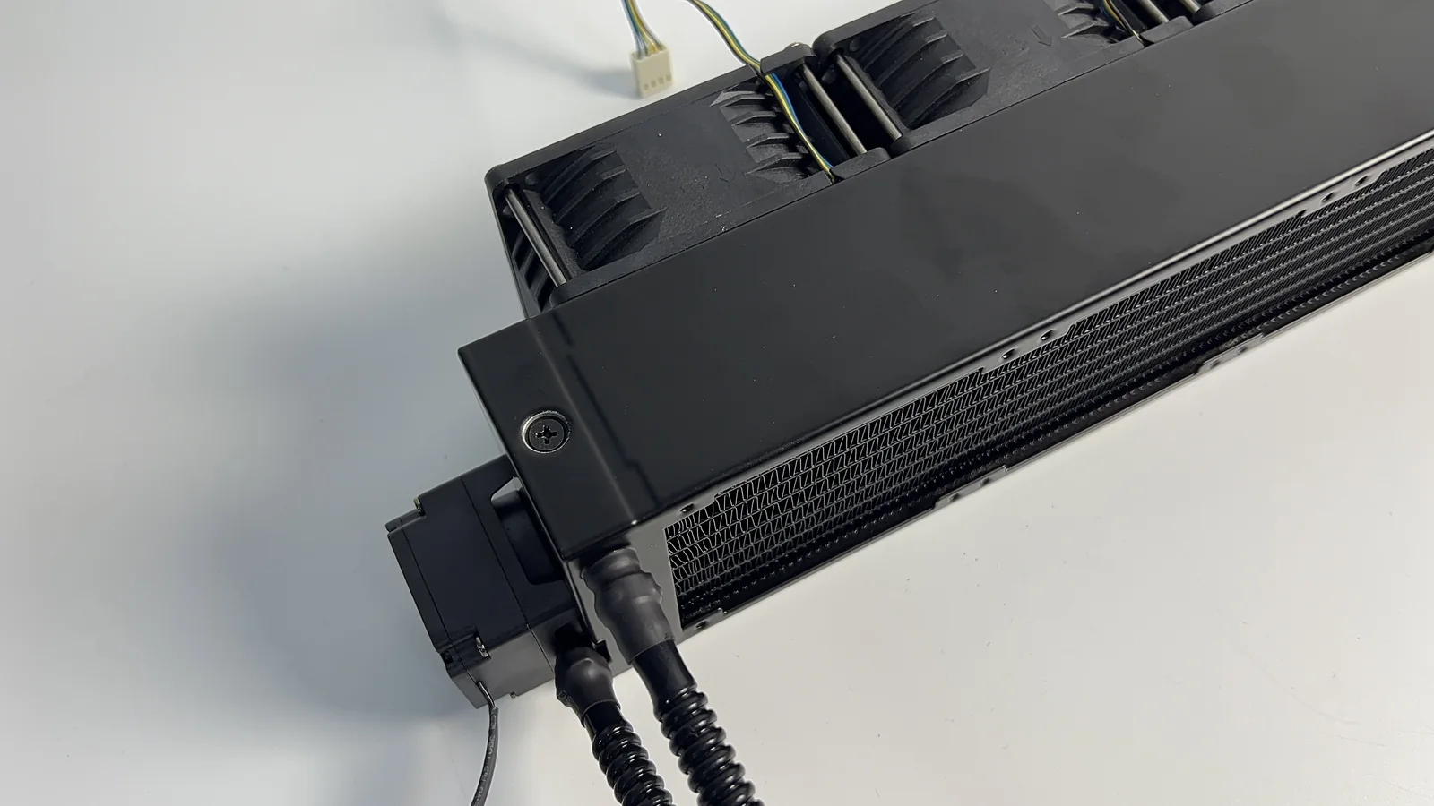
Radiator, fan and pump space, wiring, filling and maintenance sequence.
The exact hardware revision matters. A socket name, GPU family or chassis height alone is not enough to confirm fit.
Use the current drawing revision.
A marked-up layout or drawing helps us understand the space and connections available.
We can customize the following elements to suit the installation space and thermal requirements. Feasibility is checked against the complete assembly.
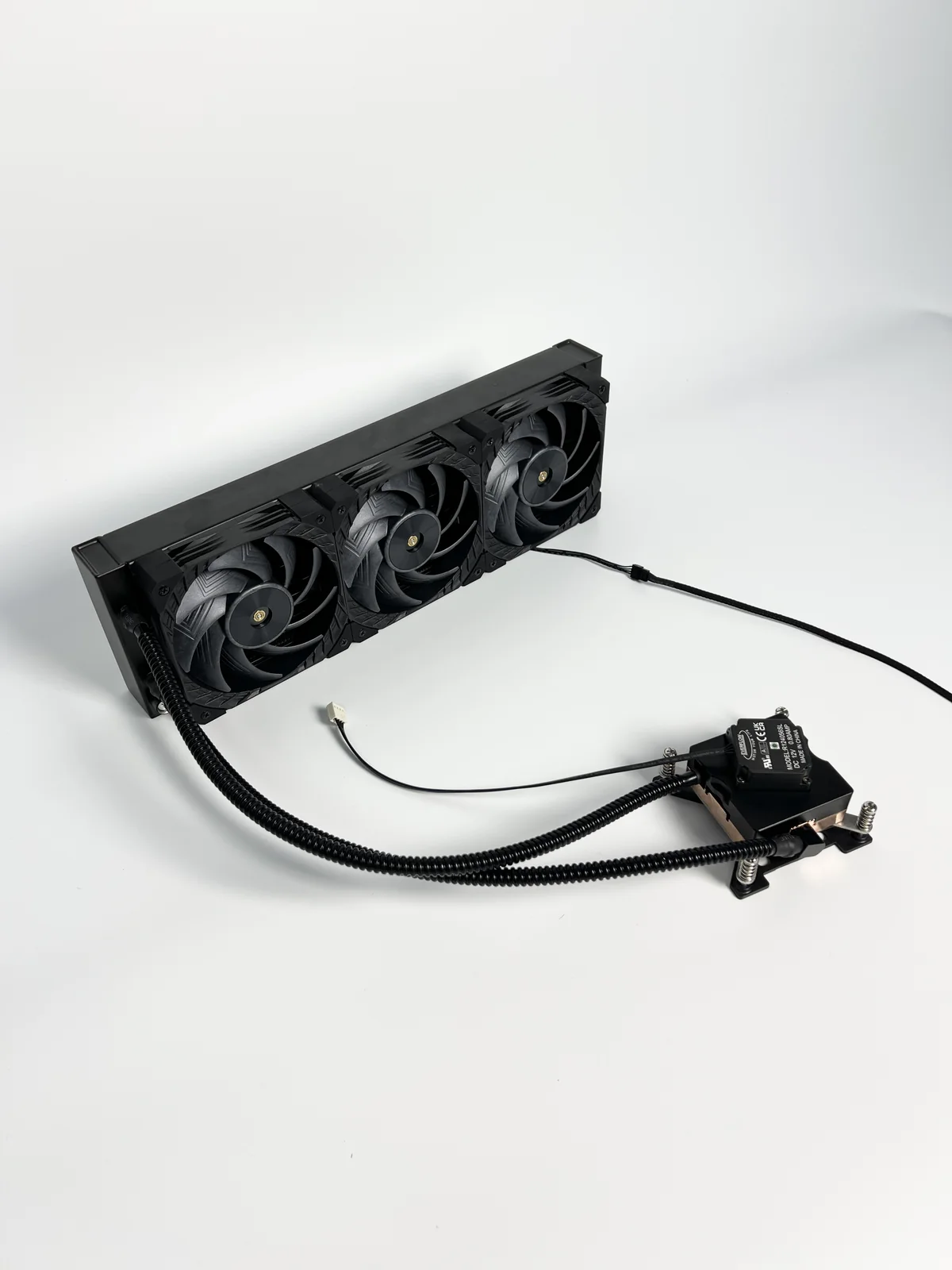
Heat-source coverage, contact surfaces and thermal interface materials.
Hole pattern, load path, brackets and installation sequence.
Internal coolant channels and connection locations for the specified cooling assembly.
Direction, length, bend space and service movement.
Port and quick-disconnect requirements where applicable.
Available length, thickness, fan arrangement and airflow.
Location, electrical interface and operating requirement.
Filling, assembly, removal and adjacent component access.
We review tool access, joining, sealing, assembly and inspection while developing the design. This helps identify features that could be difficult to make or install.

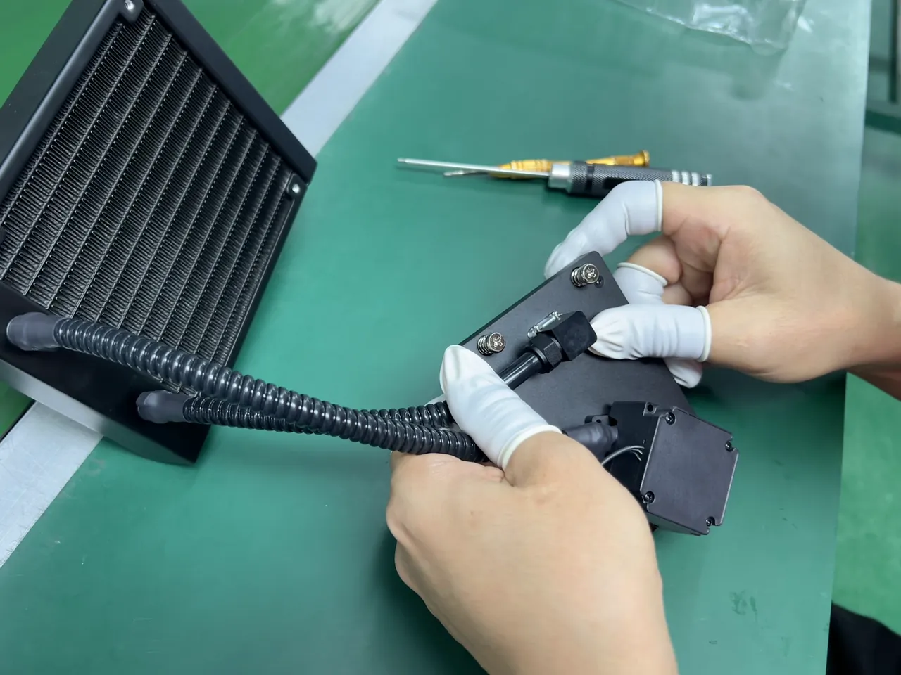
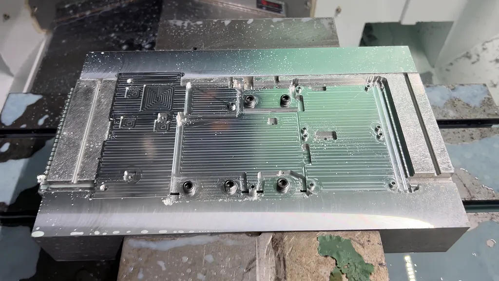
| Review area | What ThermalBro checks | Why it matters |
|---|---|---|
| Fit and access | Envelope, keep-outs, mounting and service movement | Reduces interference and installation risk |
| Machining and joining | Geometry, tool access, interfaces and sealing features | Checks that the design can be manufactured as intended |
| Assembly | Sequence, tube movement, fasteners and adjacent parts | Avoids a design that cannot be installed consistently |
| Inspection | Critical features and suitable measurement or functional checks | Agrees the features and functions to inspect on the sample |
The engineering stage defines the sample to be built, the current design revision and the checks it needs to pass. Drawings, component information and test planning are included as agreed in the quotation.
Resolve the dimensions, interfaces and operating conditions needed to start design.
Agree fit, interfaces and component arrangement.
Check manufacturing, assembly and inspection access.
Agree the drawing revision, sample quantity and tests.
Approve the applicable drawing, BOM and test scope.
The agreed design information is then used to build and evaluate the sample. Learn more about liquid cooling module prototyping.
OEM work normally starts with more customer-defined requirements or designs, while ODM work may include more joint development. The design responsibility, intellectual property and deliverables are agreed for each project.
Yes, the exact version can be reviewed when the board or platform layout, heat sources, mounting points, available space, tube route and interfaces are supplied. A shared socket or GPU name does not establish universal compatibility.
Mounting, contact structure, flow path, tube direction and length, connectors, radiator, fan and pump arrangement can be reviewed within the mechanical, thermal and manufacturing limits of the project.
Simulation is not included automatically. If required, we confirm the method, model inputs and deliverables before quotation.
A sample can be built once the key interfaces, drawing revision, sample purpose and test requirements are agreed. Any remaining assumptions should be identified before manufacture.
The affected drawing, BOM, interface and test items are identified for review before a revised sample or production version is released.
Send the drawings or CAD files you have and explain the cooling problem. We will review the design work, prototype requirements and information needed for a quotation.