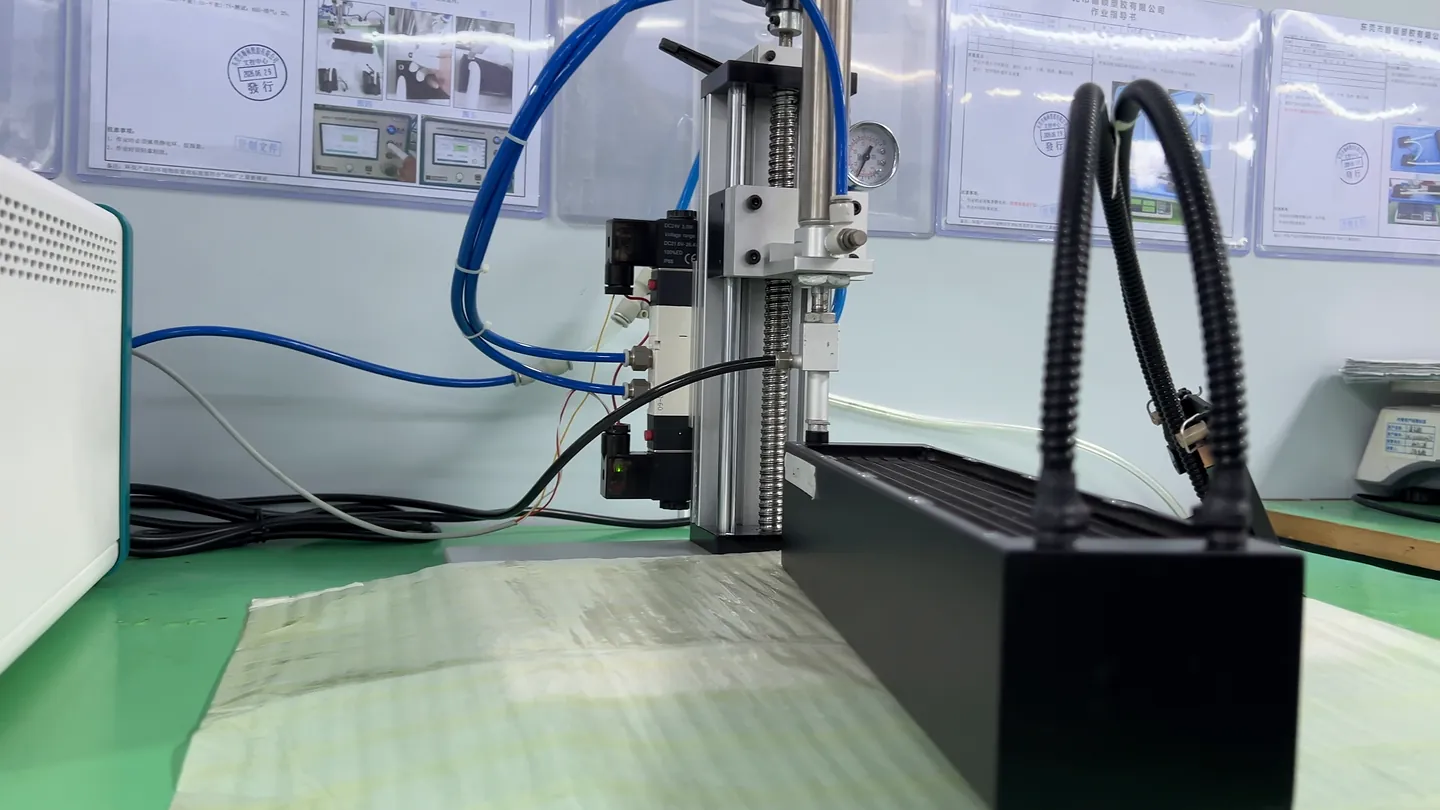
Processor Heat Collection
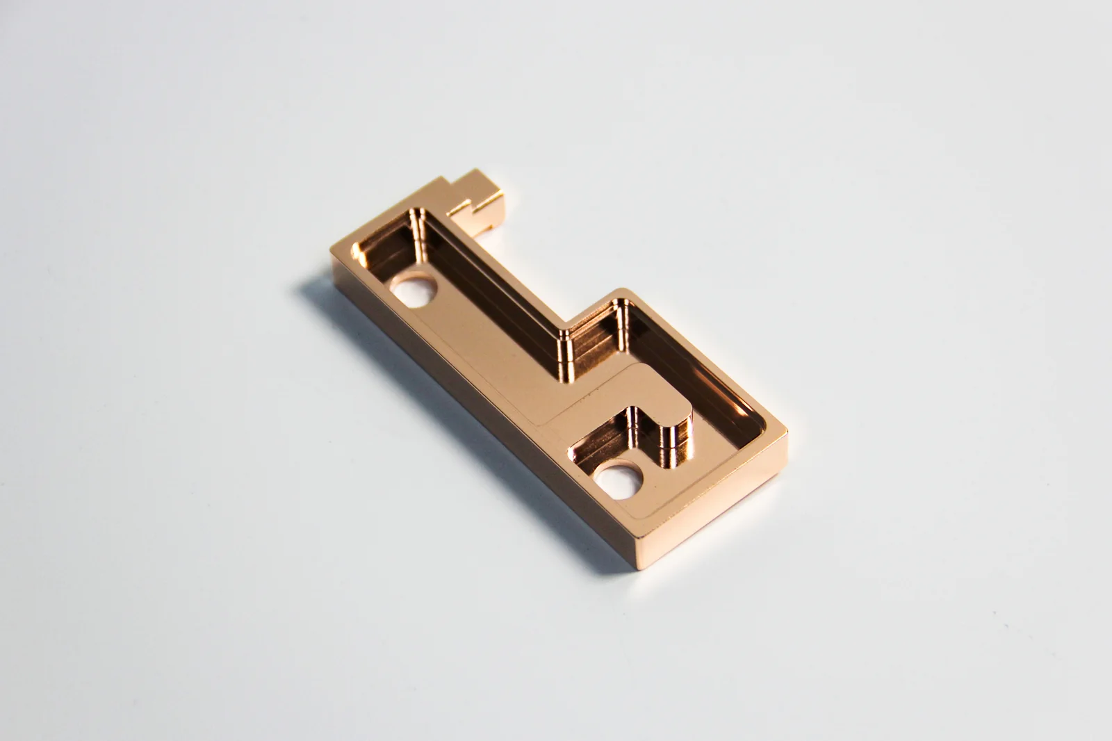
A platform-specific all-copper skived cold plate and mounting route transfer heat from the processor into the internal coolant loop.
We design and manufacture workstation liquid cooling modules for your CPU, motherboard, chassis and sustained workload. Compare the AMD and Intel examples below, then work with us to confirm mounting, tube routing, controls and testing.
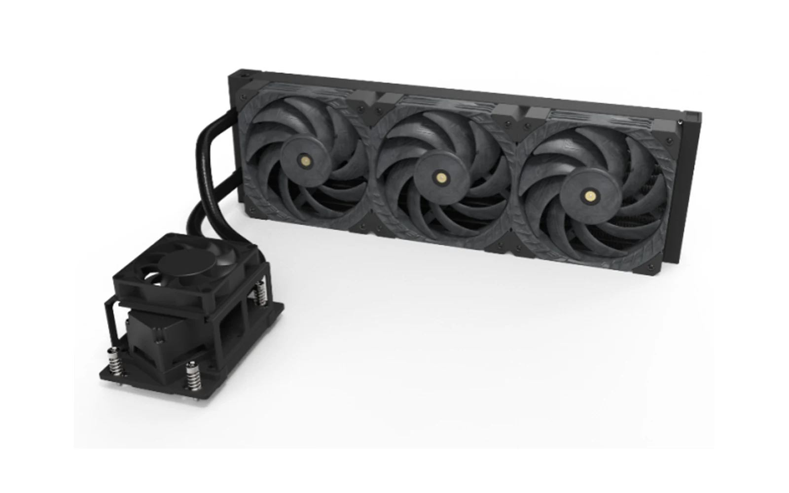
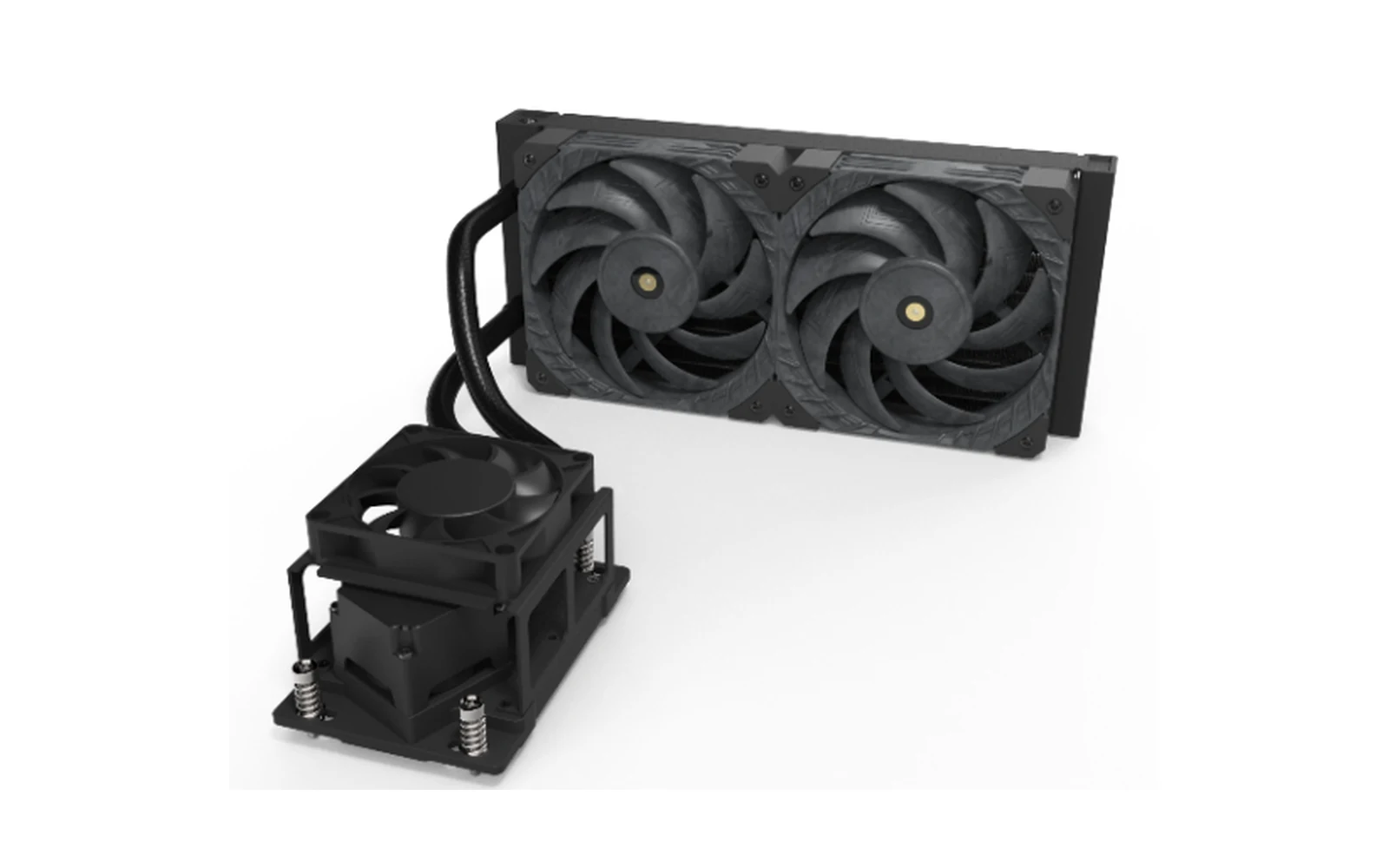
A workstation liquid cooling module is an integrated cooling assembly built around a professional CPU platform. The documented route combines a platform-specific cold plate and mounting hardware with tubing, a pump, a radiator and PWM fans so heat can move from the processor into the coolant and then to the surrounding air.
The module is installed inside an OEM or system-integrator workstation. It is not a complete workstation and does not define the final motherboard, processor, GPU, memory, storage, power supply or operating system.
A platform-specific all-copper skived cold plate and mounting route transfer heat from the processor into the internal coolant loop.
The pump moves coolant through the tubing and radiator; PWM fans then reject heat into the workstation airflow.
Compare the AMD and Intel module examples below. We confirm the exact processor, socket hardware, motherboard and chassis before selecting a configuration.
AMD platform note: EPYC 8004 processors use Socket SP6. For module entries listing both EPYC 8004 and 9004, specify the exact processor, socket and mounting kit when confirming the configuration. A grouped module reference does not mean the processors share a socket. See the AMD EPYC 8004 architecture overview (Publication 58268, Rev. 1.1, May 2024).
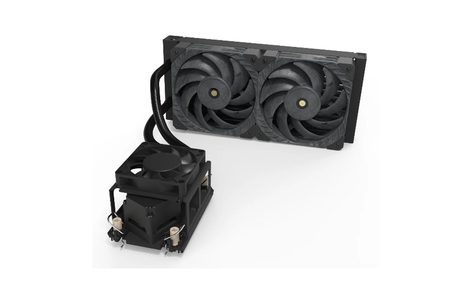
AMD module examples include 240-class and 360-class radiator configurations. Send the exact processor model, socket and motherboard revision so we can confirm the mounting and cooling requirements.
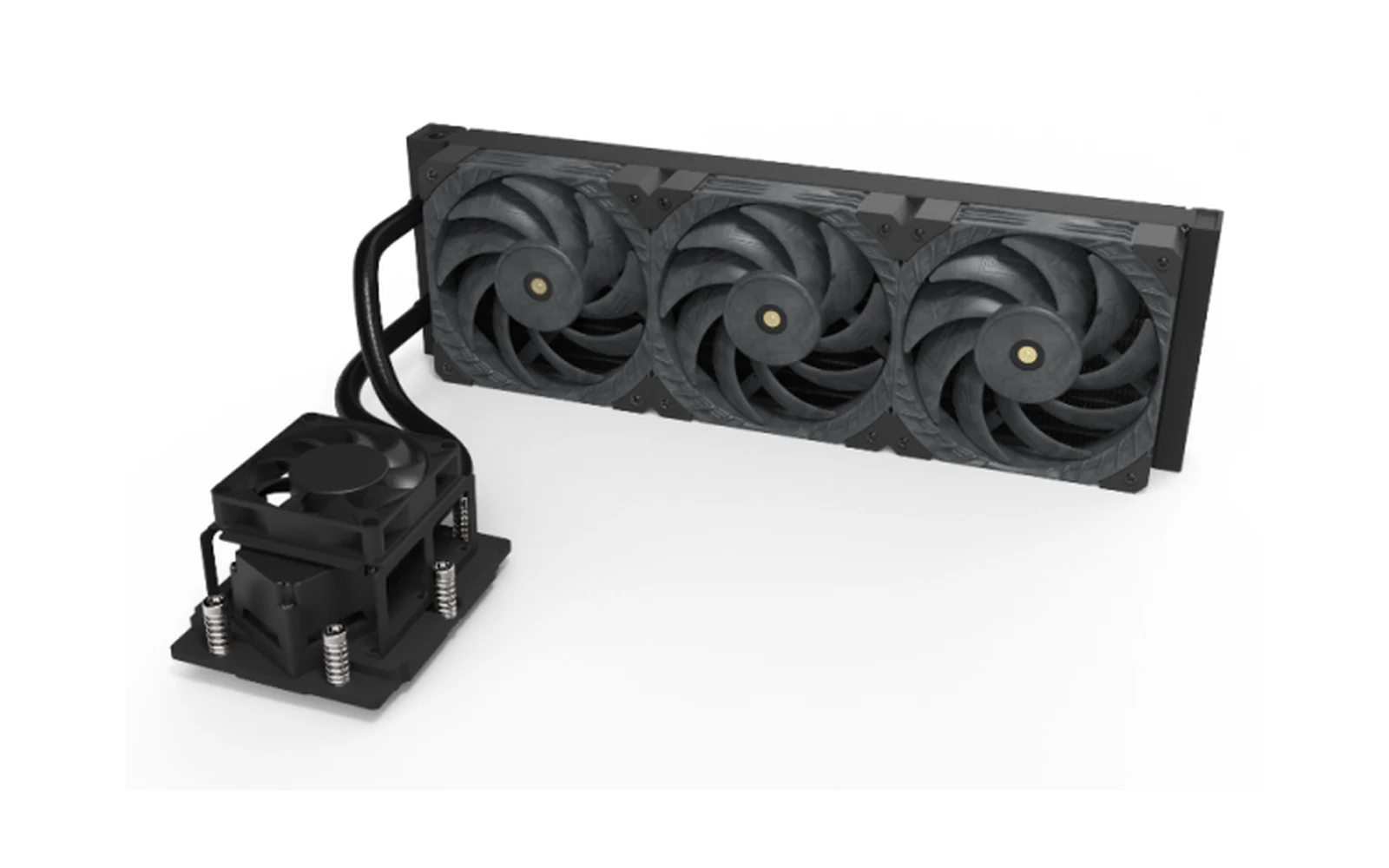
Swipe horizontally to review product views and parameters.
| Model | Processor / Socket Reference | TDP Reference | Radiator Envelope | Fans |
|---|---|---|---|---|
| DWA24012CUA1001R | AMD SP3/6 · EPYC 7002/7003 and Ryzen Threadripper series | 400 W | 278 × 55 × 120 mm | 2 × 120 mm |
| DWA36012CUA1001R | AMD SP3/6 · EPYC 7002/7003 and Ryzen Threadripper series | 600 W | 396 × 55 × 120 mm | 3 × 120 mm |
| DWA24012CUA2001R | AMD SP5 · EPYC 8004/9004 series | 400 W | 278 × 55 × 120 mm | 2 × 120 mm |
| DWA36012CUA2001R | AMD SP5 · EPYC 8004/9004 series | 600 W | 396 × 55 × 120 mm | 3 × 120 mm |
Documented TDP and dimensional values are model-selection references, not an unconditional performance or compatibility guarantee. Final results depend on the released board, chassis, workload, ambient, airflow, control and test conditions.
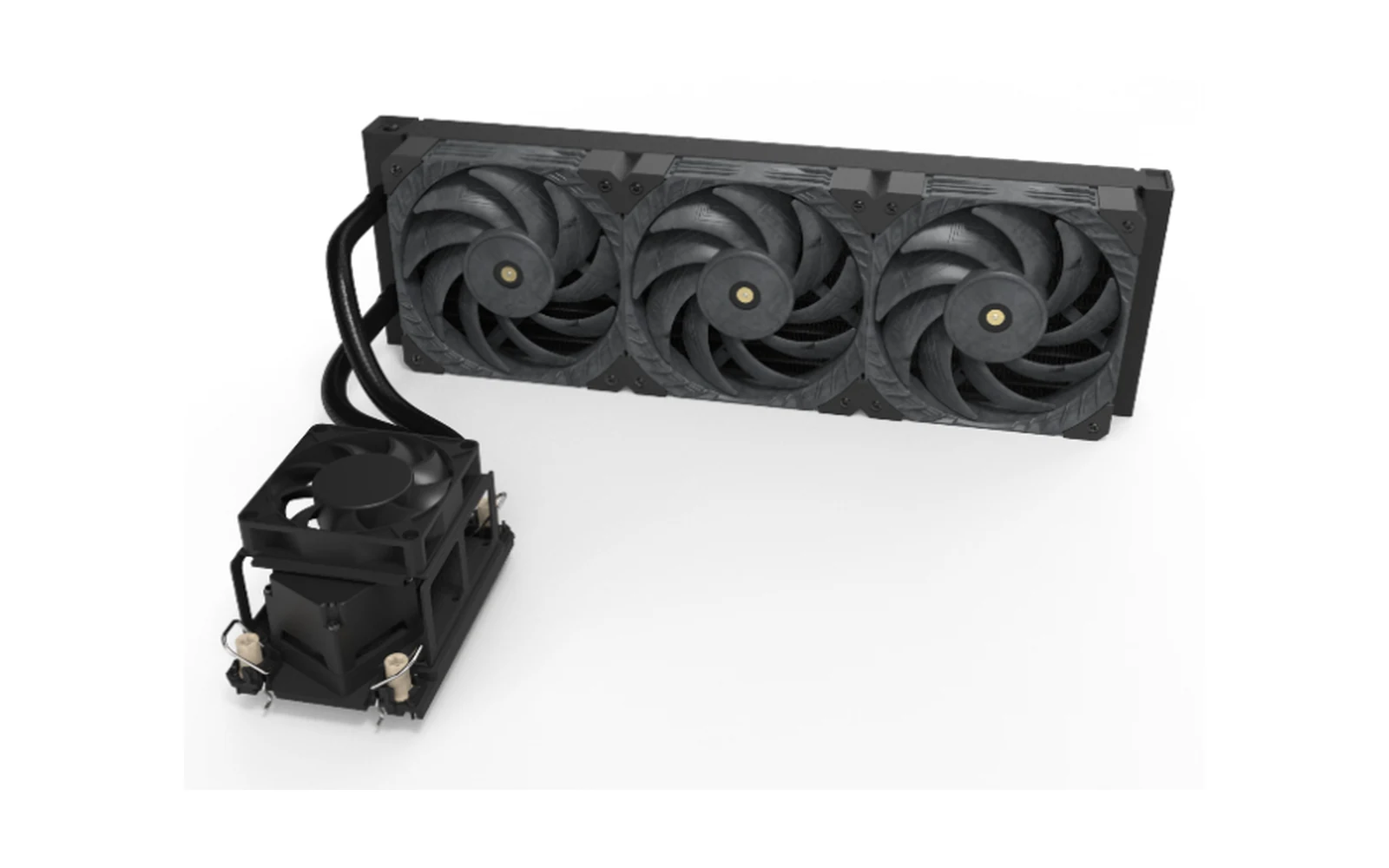
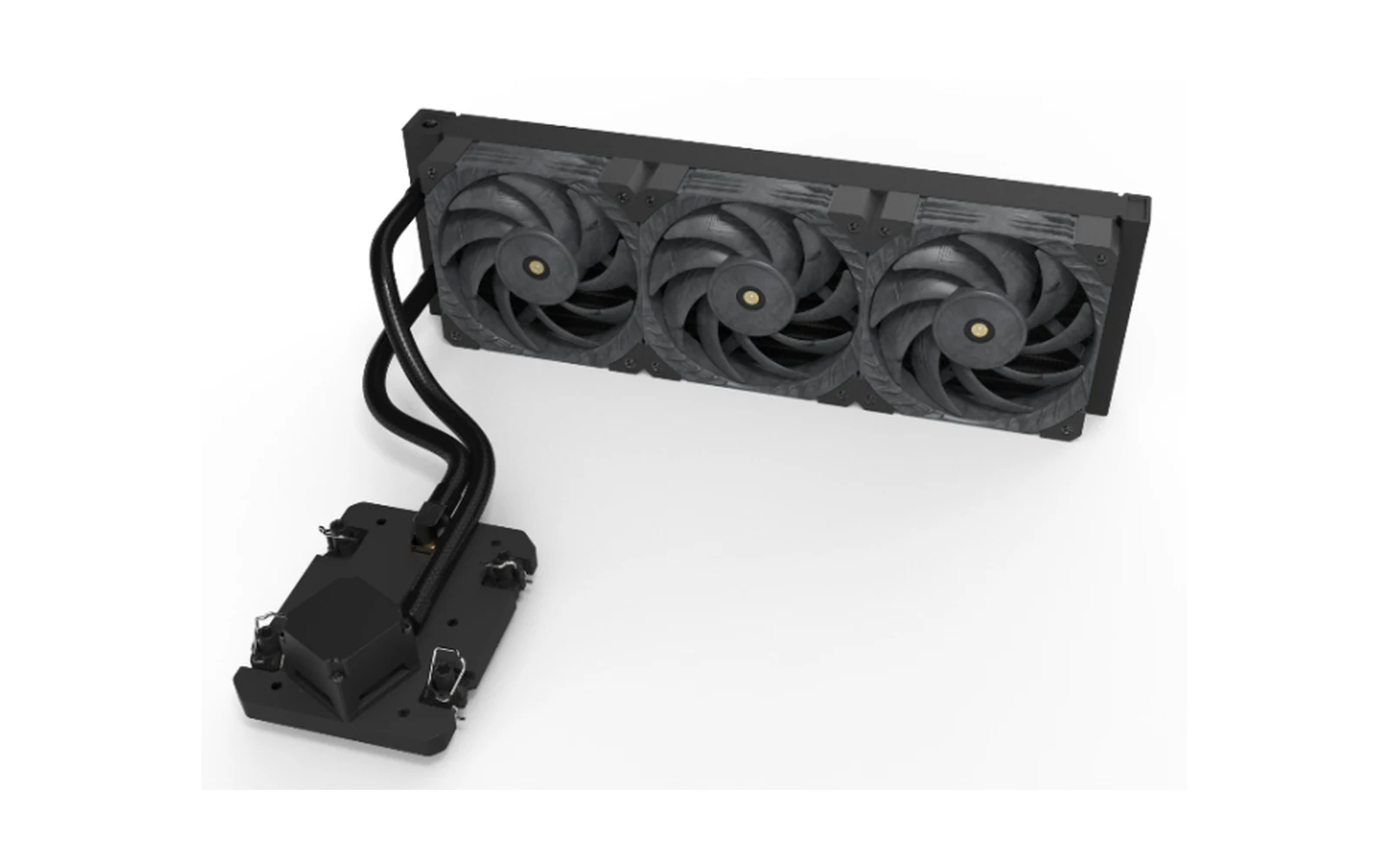
Intel module examples cover selected Xeon workstation platforms. Send the exact processor, socket and motherboard revision to confirm the appropriate mounting hardware and module configuration.
Swipe horizontally to review product views and parameters.
| Model | Processor / Socket Reference | TDP Reference | Radiator Envelope | Fans |
|---|---|---|---|---|
| DWA24012CUI1001R | Intel LGA4189 · third-generation Xeon series | 300 W | 278 × 55 × 120 mm | 2 × 120 mm |
| DWA36012CUI1001R | Intel LGA4189 · third-generation Xeon series | 400 W | 396 × 55 × 120 mm | 3 × 120 mm |
| DWA24012CUI2001R | Intel LGA4677/4710 · fourth-, fifth- and sixth-generation Xeon series | 400 W | 278 × 55 × 120 mm | 2 × 120 mm |
| DWA36012CUI2001R | Intel LGA4677/4710 · fourth-, fifth- and sixth-generation Xeon series | 600 W | 396 × 55 × 120 mm | 3 × 120 mm |
| DWA24012CUI3001R | Intel LGA7529 · sixth-generation Xeon series | 400 W | 278 × 55 × 120 mm | 2 × 120 mm |
| DWA36012CUI3001R | Intel LGA7529 · sixth-generation Xeon series | 600 W | 396 × 55 × 120 mm | 3 × 120 mm |
Documented TDP and dimensional values are model-selection references, not an unconditional performance or compatibility guarantee. Final results depend on the released board, chassis, workload, ambient, airflow, control and test conditions.
Radiator size is only one part of workstation cooling. Sustained processor load, ambient temperature, chassis airflow resistance, available radiator space, fan and pump control, acoustic targets and service access all affect the right route.
We review the board, mounting, radiator space and service access together so the module can be tested in the workstation you plan to build.
| Decision Factor | Traditional Air Cooler | Standard Consumer AIO | OEM Workstation Module | What to Confirm |
|---|---|---|---|---|
| Professional platform fit | Platform-dependent | Listed sockets only | Board and mounting review | Released board and socket hardware |
| Contact and mounting | Product-defined geometry | Product-defined geometry | Project-specific review | Contact, load and keep-outs |
| Radiator and routing | Not applicable | Standard package | Chassis-integrated route | Space, orientation and service path |
| Validation | Integrator-defined | Supplier product scope | Project-defined checks | Conditions and acceptance criteria |
Long render queues need evaluation under sustained, not momentary, CPU load.
Engineering workloads combine long CPU runs with chassis and acoustic limits.
CPU cooling must be coordinated with GPU heat and radiator space.
Repeatable thermal conditions matter when jobs run for hours.
The processor name is only the starting point. Contact geometry, mounting load, motherboard keep-outs, radiator location, tube direction, controls, installation space and service access all affect the module.
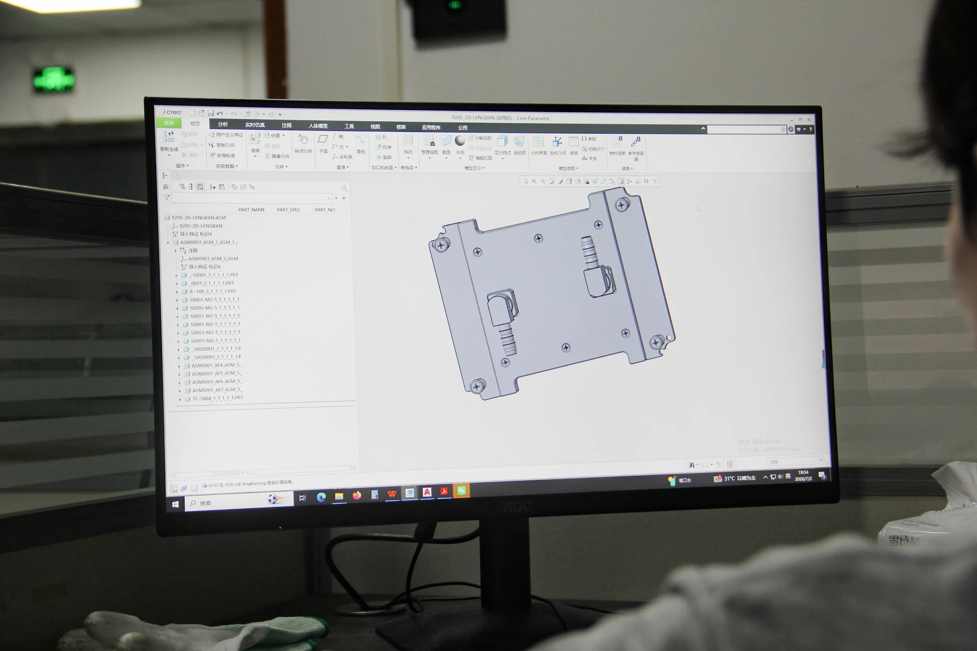
01Cold-plate contact area and platform-specific mounting02Bracket, fastener and allowable loading review03Tube length, direction and service movement04Radiator location and complete module envelope05Pump and fan power or control interface06Appearance, labels and assembly requirements where supportedEach item remains subject to the released board, chassis and engineering review. A platform name alone is not enough to confirm fit.
ThermalBro combines engineering support with CNC machining, cold-plate production, joining, module assembly and inspection. One manufacturing route reduces handoffs when a board, mounting detail or tube route changes.

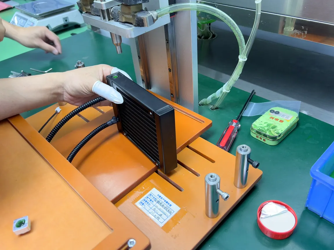
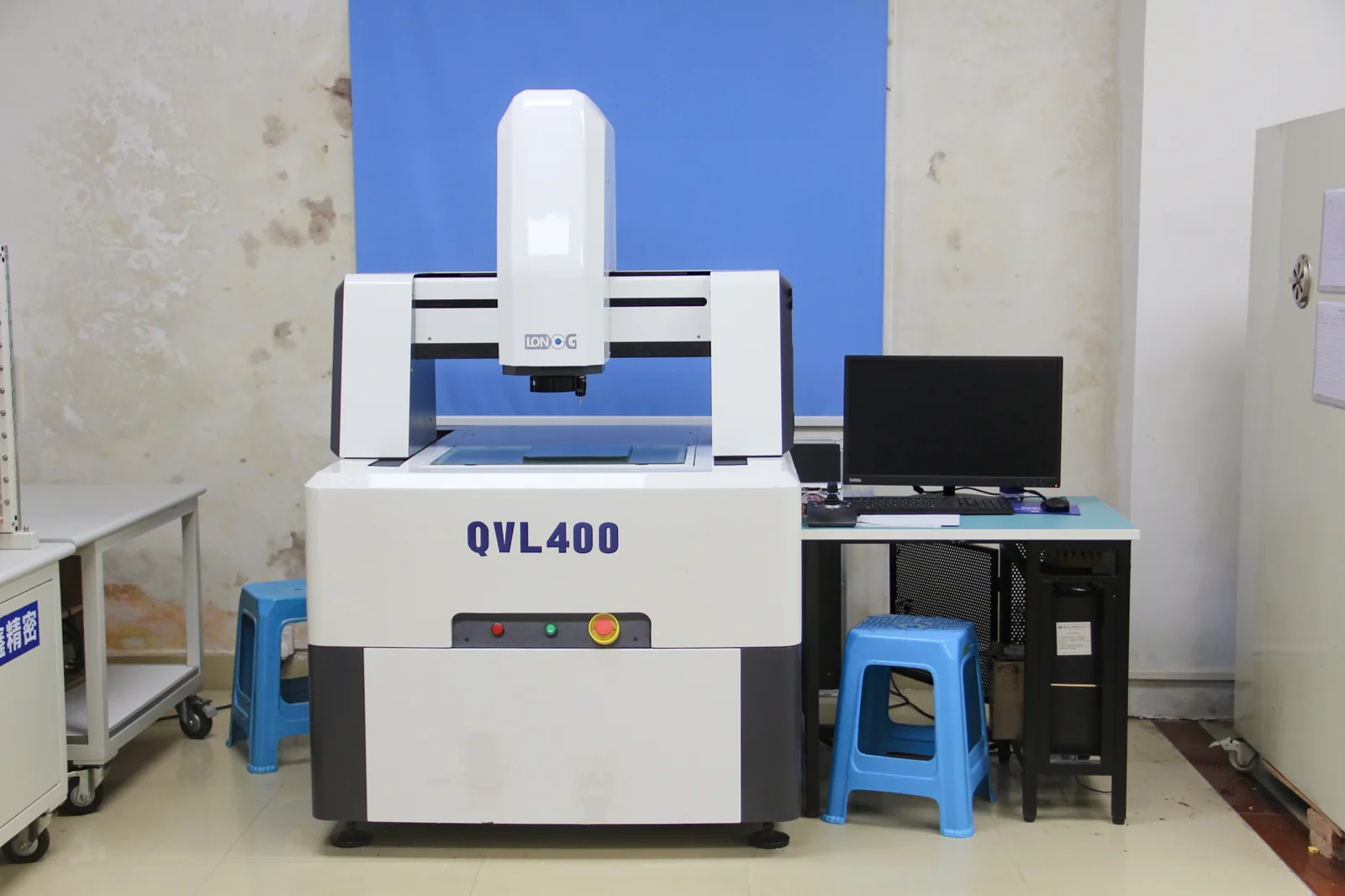
The validation plan separates fit, leak or pressure, thermal performance and environmental checks so each result answers a clear project question for the configuration that will be evaluated or shipped.
01Confirm contact, mounting, clearances, tube routing and service motion.
02Verify the coolant path against agreed conditions and acceptance criteria.
03Test the released route under defined load, coolant, ambient, airflow and control conditions.
04Keep identification, assembly details and final checks tied to the approved version.
The product version, coolant, ambient, airflow, load, measurement points, method and acceptance criteria should be recorded whenever a thermal or fluid result is used for a decision.
We review your workstation requirements, develop the module, build a prototype and test the agreed configuration before preparing for repeat production.
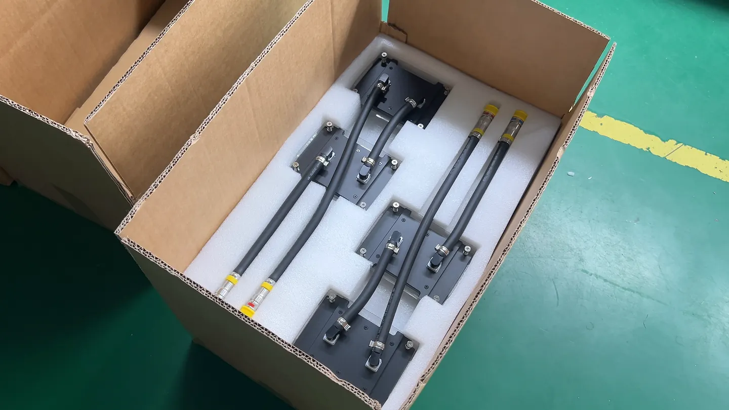
01 / INPUTSend the CPU, motherboard, chassis, workload and project context.
02 / REVIEWConfirm contact, mounting, radiator space, routing and controls.
03 / DESIGNCoordinate thermal, mechanical and fluid requirements.
04 / PROTOTYPEManufacture and assemble the agreed evaluation version.
05 / VALIDATETest fit and the approved leak, pressure, thermal or environmental scope.
06 / PRODUCTIONRetain the approved configuration and review later changes.
Clear answers on module scope, published platform references, customization, 240- and 360-class selection, acoustics, leakage testing and the inputs needed before prototyping.
Share the CPU, motherboard, chassis, sustained workload and radiator space you already know. We will review a suitable module configuration and the next steps for prototyping.