A total heat load tells a designer how much energy a cooling system must remove. It does not say where that heat enters the cold plate, how concentrated it is, or which device reaches its temperature limit first. Those details can change the contact surfaces, internal flow path and validation plan even when total power stays the same.
For a useful cold plate review, provide a heat-source map with locations, footprints, powers and operating scenarios, together with the mechanical and fluid boundary conditions. Here, heat map means an engineering description of the sources. It does not mean an unlabelled thermal-camera image or a simulated temperature plot.
Separate total heat load from local heat flux
Total power is an energy-rate input, usually expressed in watts. Average heat flux over a defined surface is power crossing that surface divided by its area. Both matter, but they answer different questions. Total load helps establish the system's heat-removal duty; local source size and position help determine how heat must spread through the interface and plate before reaching the coolant.
Consider an intentionally simplified example. In Case A, 400 W crosses a uniformly loaded 40 × 40 mm contact area. That is 16 cm², so the average heat flux is 25 W/cm². In Case B, the same 400 W crosses a uniformly loaded 20 × 20 mm contact area: 4 cm² and 100 W/cm². The cold plate envelope is unchanged in this comparison.
Same total heat input, different contact area
400 W ÷ 16 cm² = 25 W/cm²
↓ Uniform heat input over the stated contact surface.
400 W ÷ 4 cm² = 100 W/cm²
↓ Same total input, one-quarter of the contact area.
Case B has four times the average heat flux over the stated contact area. That does not predict four times the temperature rise, nor prove that either design passes. The temperature field also depends on the package, spreading through the solid, interface resistance, plate geometry, local coolant conditions and flow. These numbers are a constructed illustration, not a simulation, measurement or ThermalBro capacity rating.
The definition of area is important. A semiconductor die, package lid, interface contact patch and cold plate base can have different dimensions. Do not divide device power by the full plate outline and call the result die heat flux. Identify the surface to which each number applies and state how much of the device's dissipated heat is assumed to enter the plate. Heat leaving through other paths must be treated consistently in the model.
Map the sources for each relevant operating scenario
Give each heat source an ID and place it on a drawing with a coordinate origin, orientation and units. Record its footprint and contact height, the intended thermal interface, power under the named load case, and the temperature limit at the specified node. Attach the source of the power estimate: a component limit, a design allocation, a measurement, or a model. These forms of evidence are not interchangeable.
Eaton's custom cold plate design guidance likewise identifies component dimensions, locations and heat loads as thermal-map inputs, alongside temperature and coolant conditions. This supports collecting spatial information before evaluating a liquid circuit.
The largest total load is not always the only useful case. One workload may heavily load a compact device, while another distributes similar power across several sources. Test planning should include credible distributions that could govern local temperatures, not only the case with the largest sum. Avoid adding peaks from mutually exclusive operating modes and presenting the result as a measured simultaneous condition.
Information to include in a heat-source map
Swipe the table horizontally to compare all columns.
| Map entry | Information to provide | Why it changes the review |
|---|---|---|
| Source identity and position | Device ID, x/y reference, orientation and drawing revision | Aligns the heat input with the actual plate and mounting features |
| Contact geometry | Footprint, height, flatness requirements and interface stack | Defines where heat enters and whether each device can contact the plate |
| Load scenario | Power per source, simultaneous activity, duration and repetition | Separates distributed, concentrated and transient demands |
| Temperature criterion | Limit, measurement node and approved source | Prevents a surface reading from being mistaken for a junction limit |
| Evidence status | Measured, modeled or estimated; uncertainty and owner | Identifies which conclusions are provisional and what must be confirmed |
Transient loads also need time information. A short pulse and a sustained load with the same peak power can produce different temperature responses because heat is stored in the components and structure. Supply pulse duration, repetition, starting condition and any recovery period. Do not average away a short event that could govern a device limit; equally, do not assume a continuous peak is the normal duty without identifying that assumption.
Check the contact stack before refining the flow channels
A well-positioned channel cannot compensate for an unintended gap between the device and plate. With several devices under one plate, nominal heights, tolerance stacks, board deflection and clamping can determine which contact carries load and which interface becomes too thick. A mechanical drawing must support the thermal map.
Identify the contact surface on each device and the approved thermal interface material or the options still under review. Include the intended bond-line condition, permissible mounting loads, fastener pattern, flatness requirements and any electrical isolation needs. Use device and interface-material documentation for limits; avoid treating a generic thickness or mounting torque as suitable for every assembly.
When one device is hotter than predicted, inspect the interface and measurement method before assuming the cold plate needs more channels. A localized contact problem and insufficient coolant-side heat transfer can produce similar symptoms but require different corrections. A test that records only bulk coolant outlet temperature can miss this distinction.
Connect source locations to the fluid path and manufacturing limits
Once the source map and stack are understood, the designer can evaluate how the fluid path serves them. In a series path, coolant picks up heat as it travels, so downstream regions can see warmer fluid than upstream regions. Parallel passages can redistribute flow, but equal-looking branches do not guarantee equal flow when their hydraulic resistances differ. Source location, channel geometry and the available pressure difference belong in the same review.
Increasing local surface area or changing channel geometry may improve heat transfer while increasing pressure drop or manufacturing complexity. The loop's pump and total resistance determine the attainable flow. A model run at a prescribed flow is conditional on the system being able to supply that flow; it does not establish the installed operating point.
Boyd's liquid cold plate technical datasheet describes multiple internal constructions and links geometry optimization with thermal/hydraulic validation. It is an example of the design method and tradeoff, not evidence that ThermalBro supplies every construction or shares the listed product capabilities.
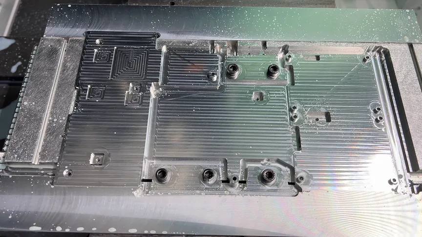
Manufacturing review must address tool access, corner radii, channel depth, thin sections, burr removal, cleaning and inspection. Channel changes may also move sealing features or reduce stiffness around a mounting point. A geometry that looks favorable in a thermal model still needs a controlled drawing and an agreed manufacturing route. Our cold plate CNC design guide covers these drawing and process decisions in more detail.
Supply the boundary conditions that make the map usable
A source map is necessary but incomplete without its surroundings. Provide fluid type and concentration, inlet temperature range at the plate, available flow or pressure-difference conditions, and any restrictions from the rest of the loop. Identify whether these are confirmed system conditions or proposed design inputs. A facility supply temperature measured elsewhere is not automatically the cold plate inlet temperature.
State the mechanical envelope, inlet/outlet interfaces, orientation constraints, mounting and service access. Include allowed wetted materials and the relevant compatibility requirements. If joining, surface finishing, cleaning, assembly or functional testing is required, place it explicitly in the supply scope. A machined open plate is different from a completed, sealed and tested fluid assembly.
For a hypothetical two-device board, assume the total design allocation is known but individual simultaneous powers and contact heights are missing. The supplier can review the envelope and drawing completeness. It cannot confidently locate the governing hot spot or confirm shared contact. The next actions are specific: the electronics owner supplies a scenario-by-source power table, the mechanical owner provides the height/tolerance stack, and the system owner confirms fluid conditions. Request those inputs before treating a preliminary channel arrangement as a validated design.
Validate the local temperatures as well as the total heat balance
Agree what the model and physical test are intended to establish. A numerical model can compare options under stated assumptions; a measured result applies to a particular build and test condition. Keep the source map revision, material properties, interface assumptions, fluid conditions and acceptance limits associated with each result. A smooth temperature plot is not a substitute for those inputs.
Use representative source footprints and locations in a heater test. A single large heater with the right total watts can miss the concentrated input that governs the actual device. If the fixture differs from the product, document the difference and explain which conclusions it can support. Match the thermal interface and mounting condition where they materially affect the question being tested.
Validate the local heat path and the supplied fluid conditions
Swipe the table horizontally to compare all columns.
| Validation question | Evidence to collect | What it does not establish alone |
|---|---|---|
| Do the relevant devices stay within limits? | Device or defined surface temperatures at the agreed load cases and conditions | A surface measurement does not directly prove a junction limit |
| Does the loop supply the modeled conditions? | Plate inlet temperature, flow and pressure difference at the tested setting | A nominal pump specification is not an installed flow measurement |
| Is contact consistent with the model? | Assembly revision, mounting procedure and interface condition | A good result from one different fixture cannot validate the product stack |
| Is the energy balance plausible? | Electrical heat input and coolant heat pickup with losses and uncertainty considered | A reasonable bulk balance can coexist with a local hot spot |
For single-phase coolant, a bulk check can compare heat pickup with mass flow × specific heat × coolant temperature rise. Use fluid properties appropriate to the composition and temperature, and account for heat stored during transients or lost through other paths. Sensor uncertainty matters especially when the inlet/outlet temperature difference is small. This check helps investigate inconsistent data; it cannot replace local temperature measurements.
An infrared image can help locate accessible surface hot regions, but its interpretation depends on emissivity, reflections, line of sight and operating state. It does not directly supply device power or reveal a hidden junction temperature. Label it as measured surface-temperature evidence and keep it separate from the design's power-input map.
Prepare a cold plate review package
Send the controlled 3D model and 2D drawing together with the annotated source map, scenario table, contact stack and temperature criteria. Add fluid conditions, interfaces, material and process requirements, prototype/production quantities and the validation questions. Flag missing entries with an owner instead of filling them with plausible-looking numbers.
ThermalBro can review drawing-based cold plates and fluid parts through its CNC machining service. Identify whether the request is machining only or also includes joining, assembly and functional checks. For a complete cooling module, state that broader scope so the discussion includes the rest of the thermal path.
Questions before sending a heat-source map
Can total watts be enough for an initial discussion?
It can support an early scope conversation and system-level heat-load estimate. It is not enough to establish local device temperatures or finalize a plate serving multiple or concentrated sources. Provide the missing distribution before relying on a design conclusion.
Do we need CFD before contacting a supplier?
No. An annotated drawing and source-by-scenario table are useful first inputs. The review should determine whether calculation, simulation, testing or a combination is needed for the specific decision. An unsupported simulation is less useful than a clear set of traceable inputs.
Does a larger plate automatically solve a small hot spot?
No. Extra area is useful only if heat can spread to it and transfer to the coolant within the allowed temperature rise. Contact resistance, base geometry, channel position and flow still matter. Review the complete local heat path before changing the outside dimensions.