
Published reference
- LC630W / LC245W-4
- Documented chassis fields
- Radiator positions
We integrate workstation cooling around your chassis, CPU, GPUs and workload. LC630W and LC245W-4 are starting configurations for local AI, rendering, CAE and scientific computing, with hardware and delivery scope agreed for each project.
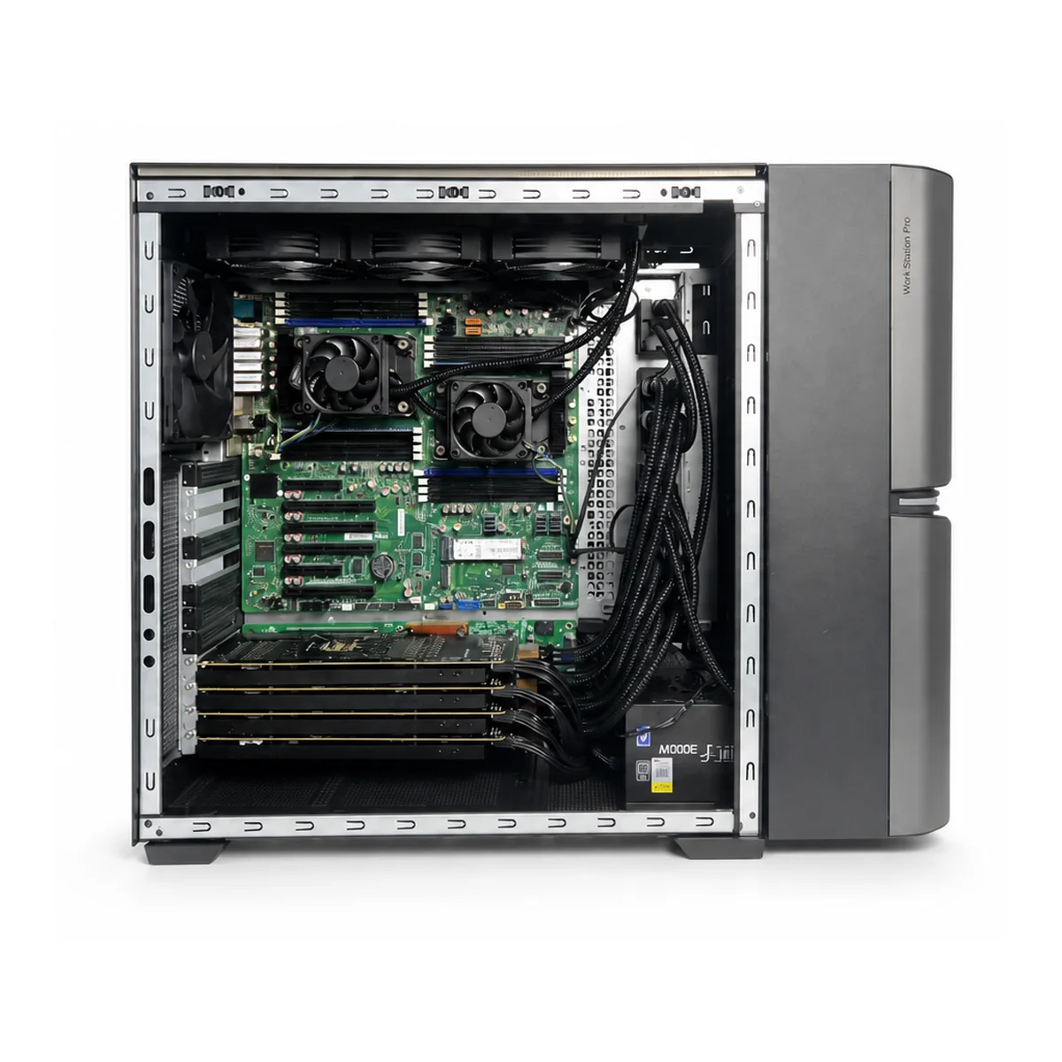
An integrated liquid-cooled workstation system coordinates the workstation chassis, motherboard format, PCIe and storage layout, CPU and GPU liquid loops, pumps, manifolds, radiators, airflow and service access around one approved configuration.
Airflow is still required for memory, VRM, storage, power components and other heat sources that are not on the liquid loop. The final CPU, GPUs, memory, storage, power supply, software and delivery documents are defined by the project BOM.
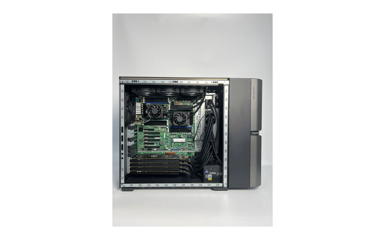
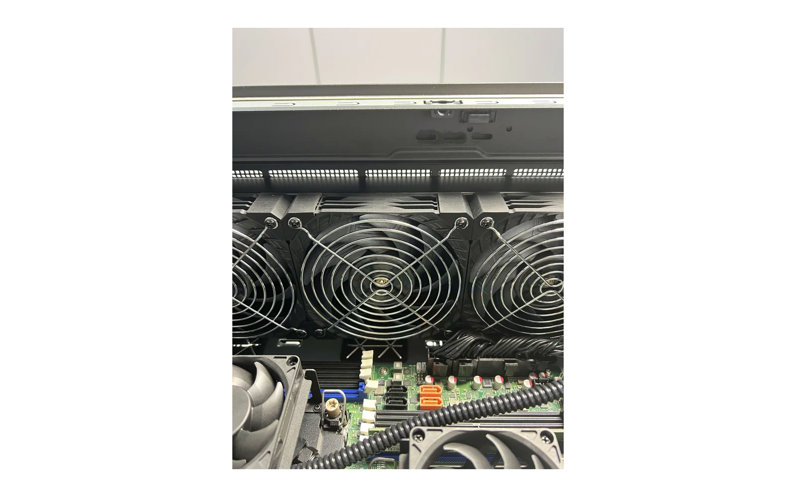
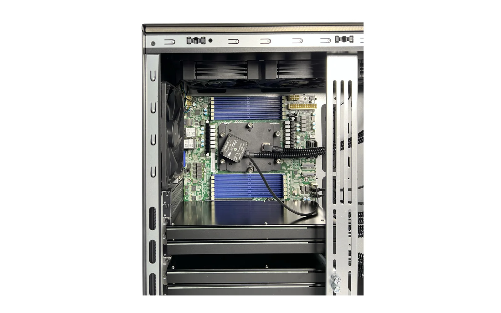
Compare LC630W and LC245W-4 by enclosure size, radiator layout, storage and service access. Final hardware compatibility and cooling performance are confirmed for your project.
LC630W is the narrower published workstation chassis reference. It combines the documented motherboard formats with eight PCI slots, front dual-360 mm radiators, two pump and distribution groups and tool-free left and right side panels.
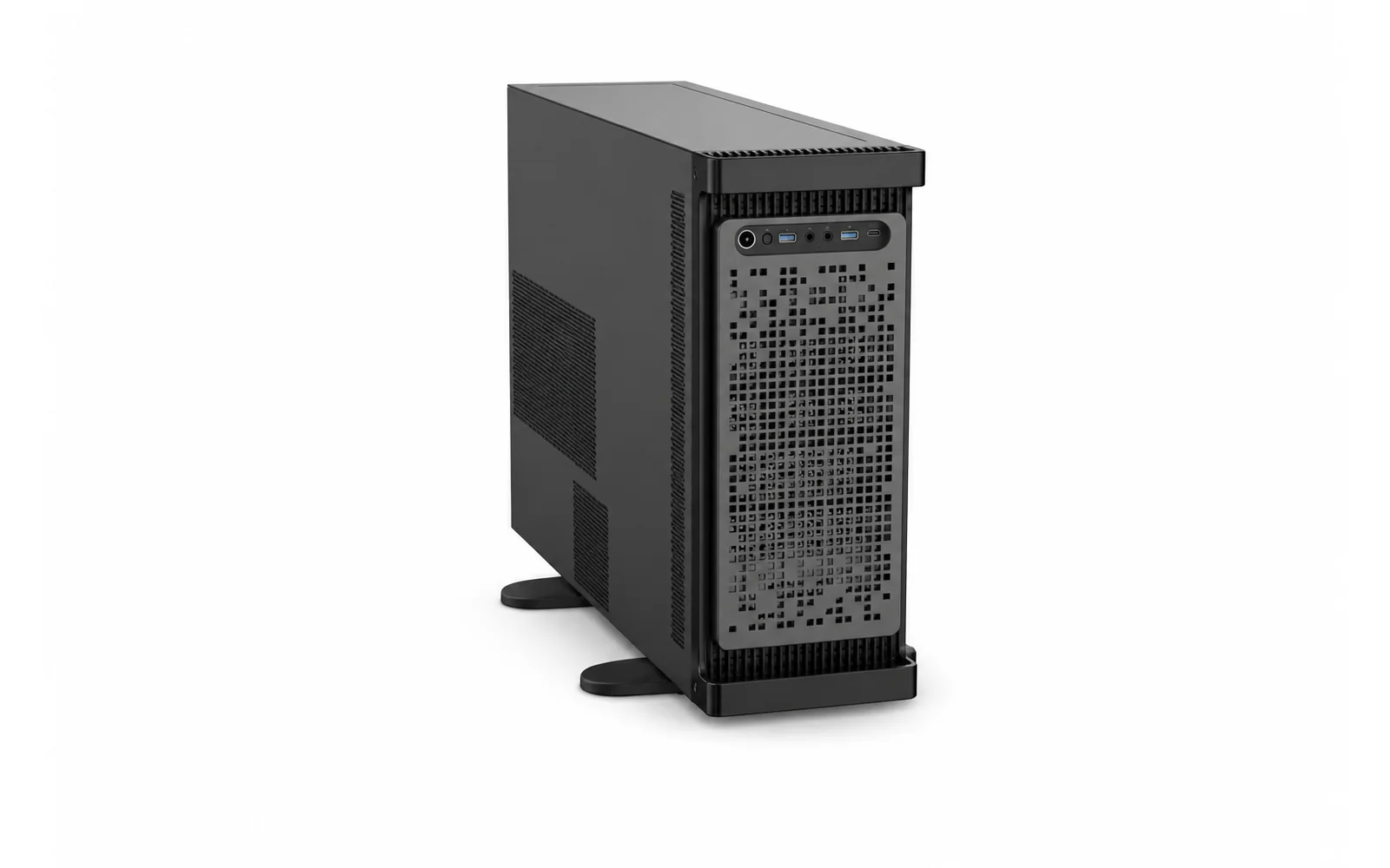
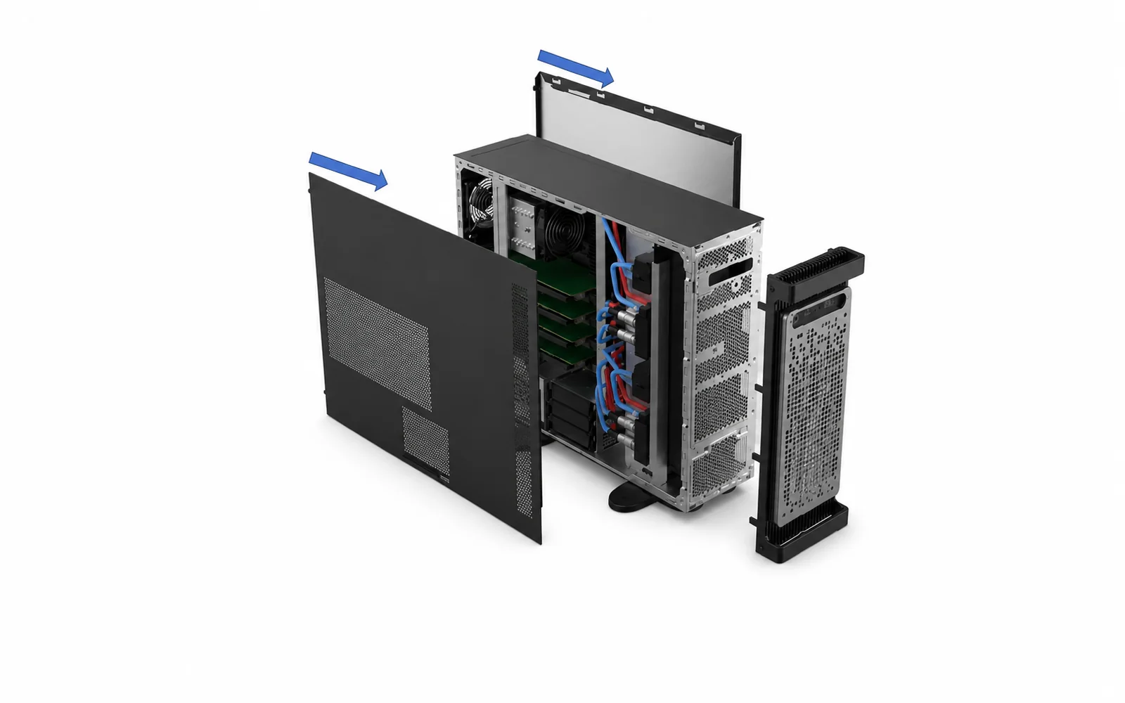
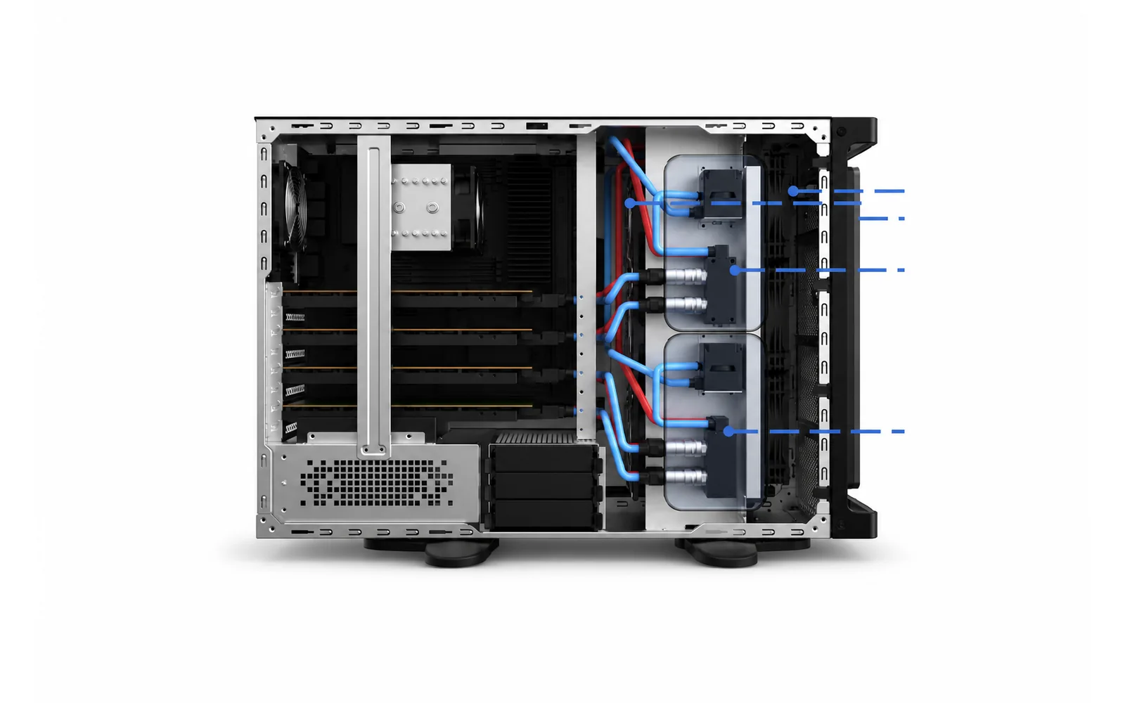
| Published Field | LC630W Reference |
|---|---|
| Motherboard formats | ATX / EATX / CEB / EEB |
| Front controls and I/O | Power / Reset; HDD LED / Power LED; 2 × USB 3.0; 1 × MIC; 1 × AUDIO; 1 × Type-C. The source material notes that interfaces can be blocked off. |
| Storage | 4 × 3.5-inch internal; the documented four-GPU installation reference shows 3 × 3.5-inch; 2 × 2.5-inch internal. |
| PCI expansion | 8 slots; standard graphics-card brackets; published 4090 liquid-cooling reference. |
| Radiator and fan layout | Front dual 360 mm radiators; 6 × 120 × 25 mm or 6 × 120 × 38 mm fans; rear 1 × 90 × 25 mm fan; optional rear 140 × 25 mm fan module. |
| Pump / distribution reference | 2 groups. The published material references two 450 W GPU liquid-cooling plates per group; the final GPU configuration requires review. |
| Power-supply structure | ATX power-supply structure. |
| Tool-free documented panels | Left and right side panels. |
| Published dimensions | 452 mm high with feet / 437 mm without feet × 174.5 mm wide × 648 mm deep. |
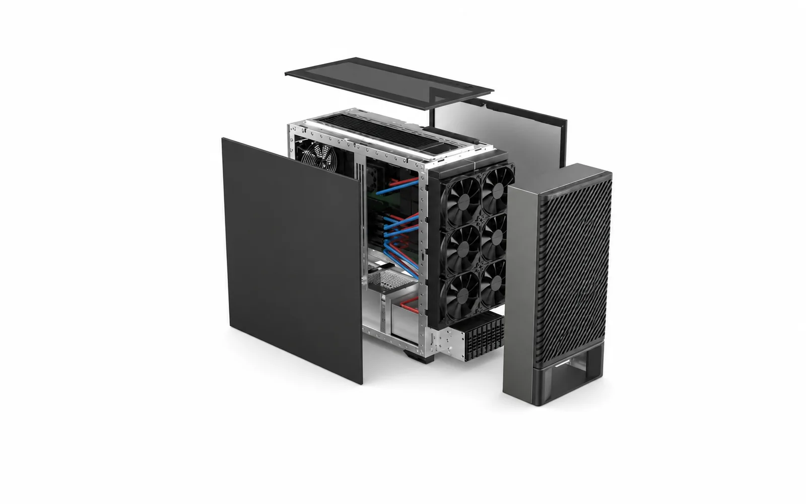
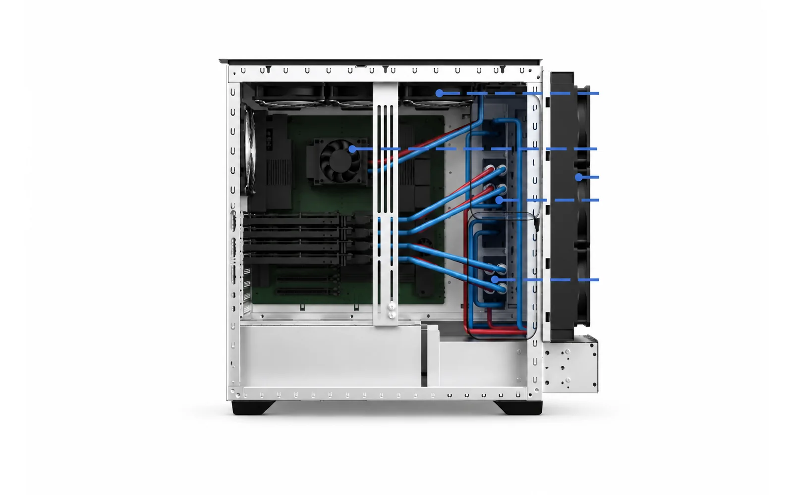
LC245W-4 provides a wider published chassis reference with the same documented motherboard-format range and eight PCI slots. Its layout adds one top 360 mm radiator position to the front dual-360 mm arrangement.
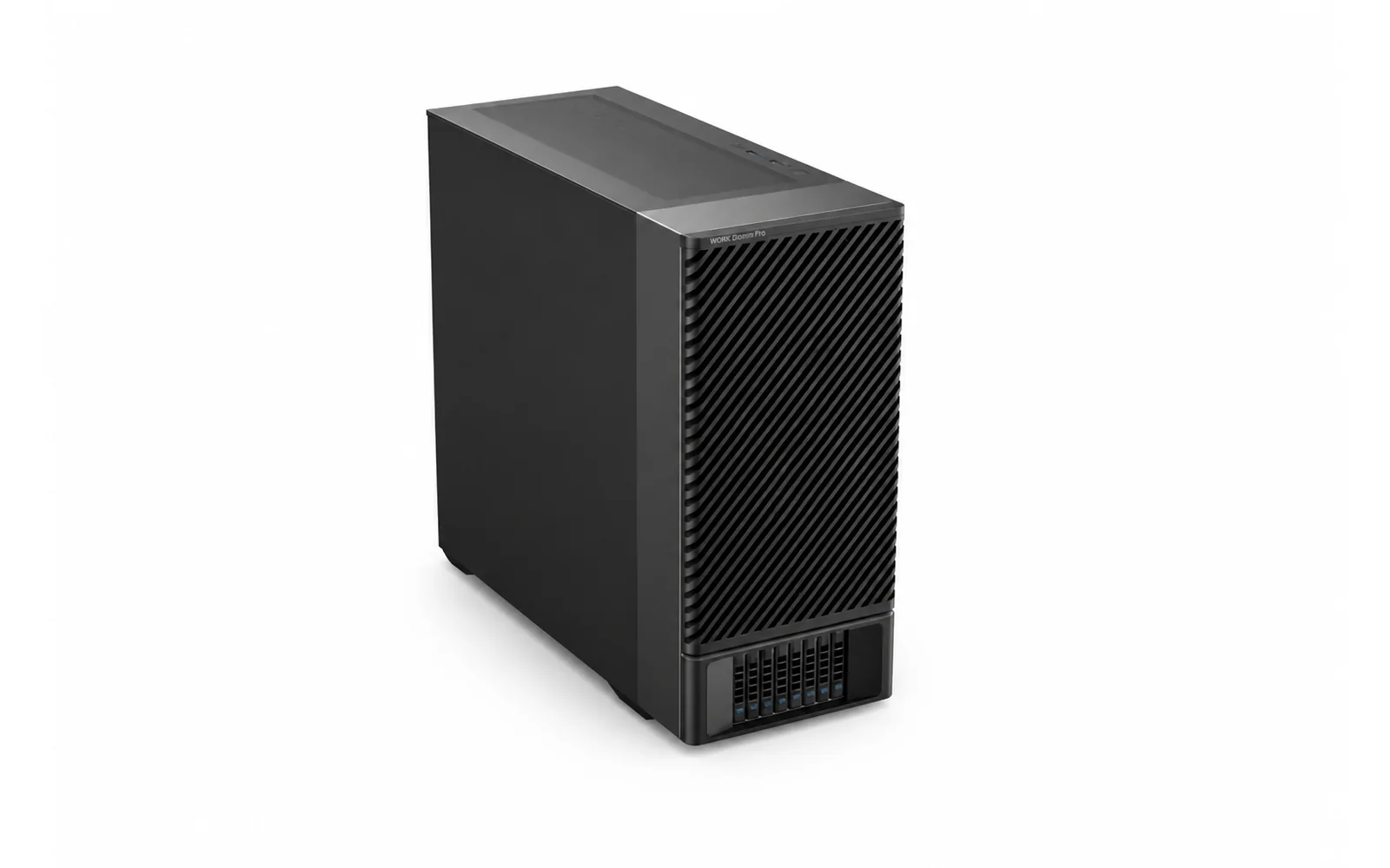
| Published Field | LC245W-4 Reference |
|---|---|
| Motherboard formats | ATX / EATX / CEB / EEB |
| Front controls and I/O | Power / Reset; HDD LED / Power LED; 2 × USB 3.0; 1 × MIC; 1 × AUDIO; 1 × Type-C. The source material notes that interfaces can be blocked off. |
| Storage | 8 × 2.5-inch external + 3 × 2.5-inch internal. |
| PCI expansion | 8 slots; standard graphics-card brackets; published AMD GPU and 4090 liquid-cooling references. |
| Radiator and fan layout | Front dual 360 mm radiators plus one top 360 mm radiator position; front 6 × 120 × 25 mm or 6 × 120 × 38 mm fans; rear 1 × 140 × 25 mm fan. |
| Pump / distribution reference | 2 groups. The published material references two 450 W GPU liquid-cooling plates per group; the internal layout also marks a CPU pump loop. |
| Power-supply structure | ATX power-supply structure. |
| Tool-free documented panels | Top, left and right panels. |
| Published dimensions | 530 mm high with feet / 510 mm without feet × 245 mm wide × 610 mm deep. |
These values describe the published chassis and liquid-cooling references. GPU generation, cold-plate fit, total heat load, power delivery, storage population and final system performance must be reviewed for the released project configuration.
Choose a module when your team already controls the chassis and system BOM. Choose an integrated platform when enclosure, liquid loops, expansion, storage, assembly and validation need to be reviewed together.
| Decision factor | Cooling module only | Integrated workstation platform | Separate component sourcing |
|---|---|---|---|
| Chassis and hardware BOM | Defined by customer | Reviewed with the integrated project scope | Defined and coordinated by customer |
| Liquid-loop packaging | Module-level interface | Coordinated with expansion, storage and service access | Coordinated across suppliers by customer |
| Assembly responsibility | Customer / system integrator | Defined in the approved delivery scope | Customer / system integrator |
| Validation | Module checks plus customer system validation | Project-defined module and complete-system validation | Customer creates the combined plan |
| Best fit | Existing released workstation architecture | New or revised liquid-cooled workstation program | Experienced internal integration team |
We review your hardware and workload before finalizing the cooling layout. The quotation identifies included components, customer-supplied hardware, software and testing.
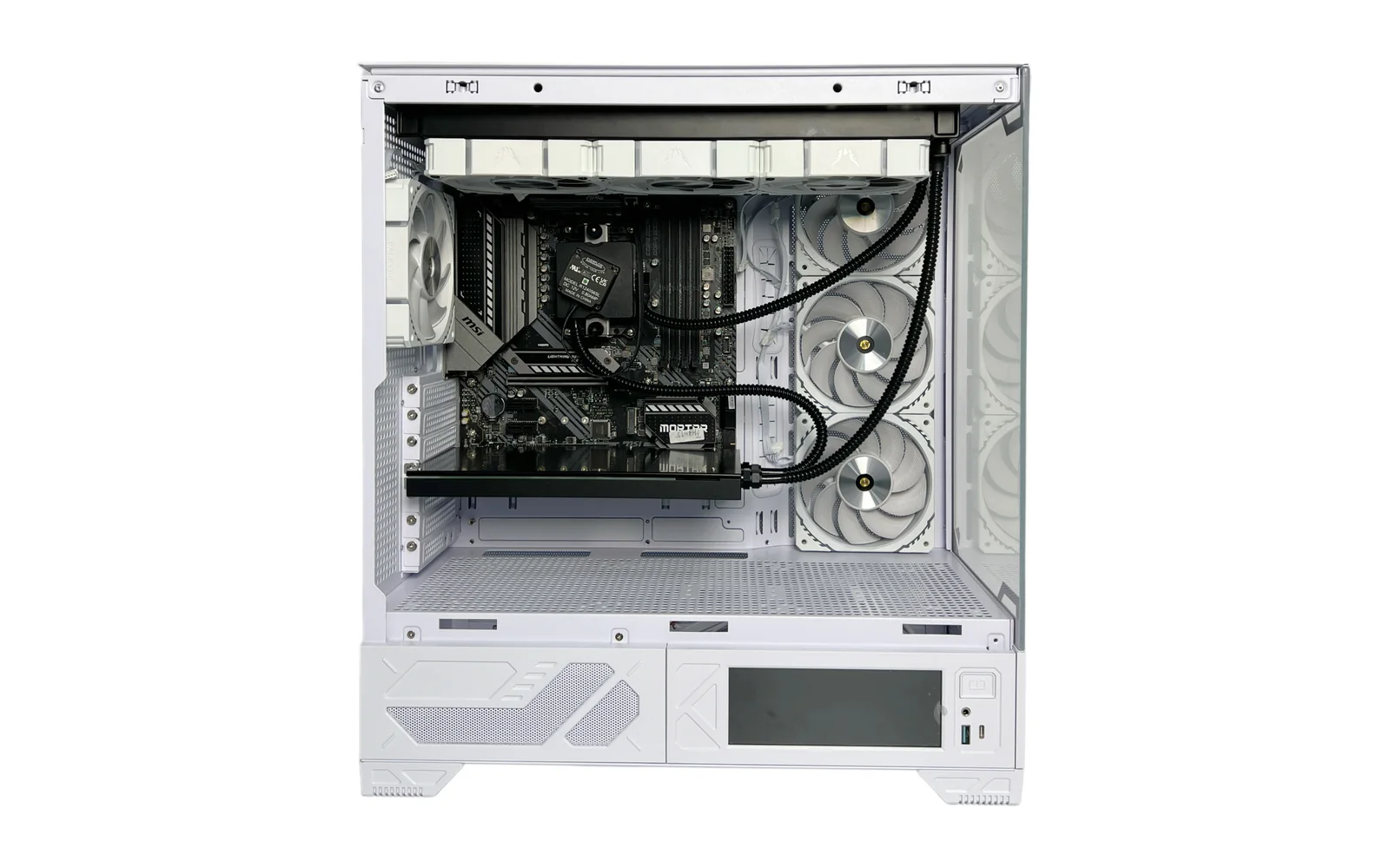
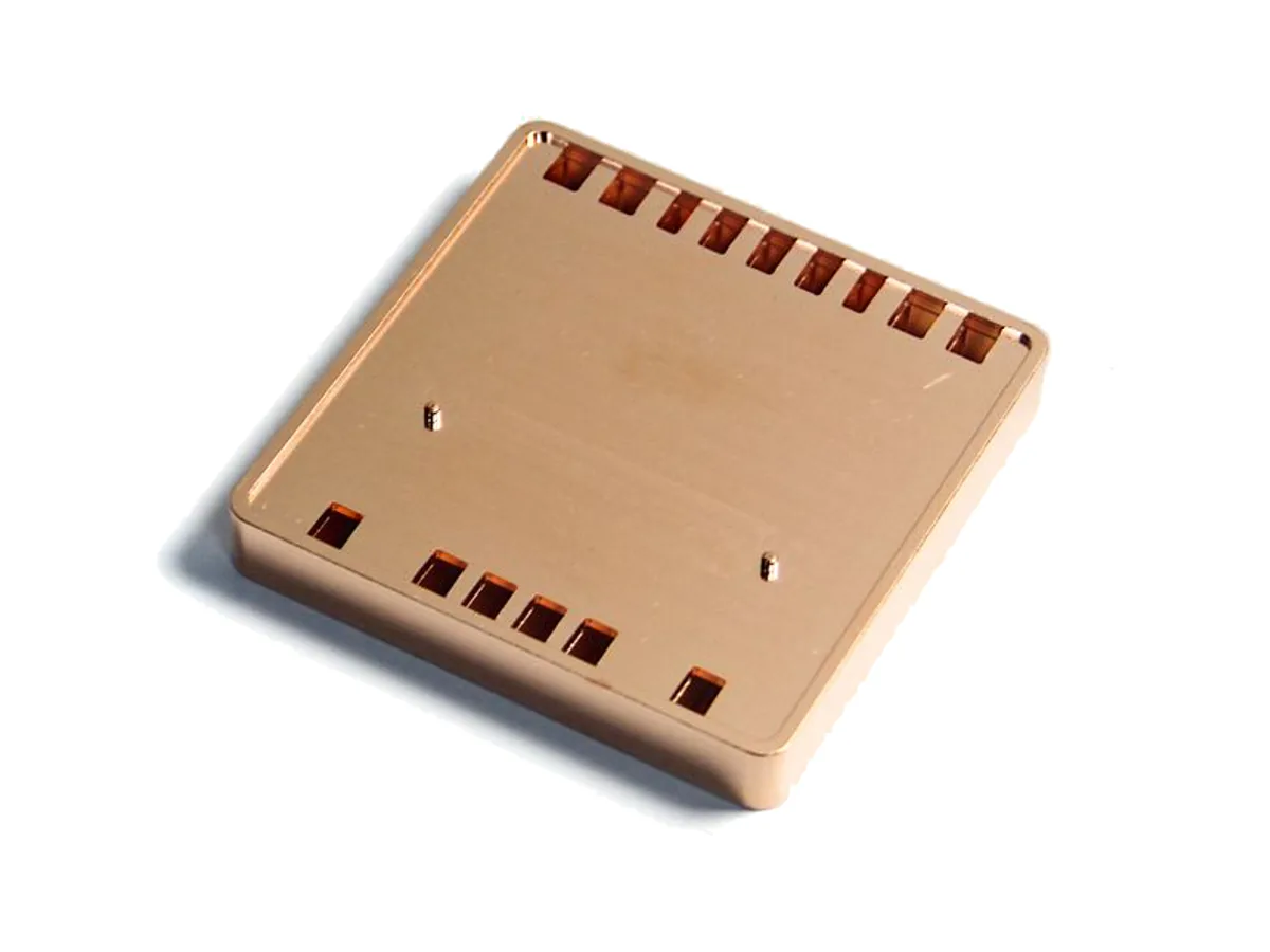
We combine thermal and mechanical design, cold-plate production, module assembly and workstation integration. The agreed drawings and hardware configuration guide prototyping and production.




A module can pass its own checks and still require complete-system validation after installation with the final board, GPUs, power, storage, controls and software. The applicable plan is defined with the approved configuration, workload, ambient conditions and acceptance criteria.
We agree the hardware and supply scope, build the prototype, test it under the intended workload and document the configuration for delivery.
Provide CPU, GPUs, board, expansion, storage, power, environment, quantity and milestones.
Map heat sources, liquid loops, radiator positions, airflow, controls and service access.
Confirm included BOM, customer-supplied items, project outputs and test conditions.
Review fit, routing, access and workmanship in the approved prototype configuration.
Run the agreed checks, record results and update the configuration where required.
Freeze the approved BOM and version, then prepare agreed build and test information.
Clear answers about the product definition, two published reference systems, four-GPU conditions, delivery scope, validation inputs and certification planning.
An integrated liquid-cooled workstation coordinates the chassis, motherboard and expansion layout, CPU and GPU cooling paths, pumps, manifolds, radiators, airflow and service access around an approved configuration. It does not automatically mean that every compute component, operating system or software package is included; those items are defined in the project BOM and delivery scope.
A workstation liquid cooling module is supplied for installation in a chassis and system architecture controlled by the customer or system integrator. An integrated workstation project reviews the enclosure, expansion, storage, liquid loops, assembly, approved hardware configuration and complete-system validation together.
Both references document ATX, EATX, CEB and EEB motherboard formats and eight PCI slots. LC630W is the narrower chassis reference and documents front dual-360 mm radiators, while LC245W-4 is wider and adds a top 360 mm radiator position to its front dual-360 mm layout. Their storage, rear fan, panel access and dimensions also differ, so the final choice depends on the required hardware and service layout.
The published material shows four-GPU, 4090 and 450 W GPU liquid-cooling references in these architectures. That is not universal compatibility. The exact GPU board, cold plate, PCIe spacing, total heat load, power delivery, radiator capacity, controls and remaining chassis airflow must be reviewed before a four-GPU configuration is approved, especially for a newer 600 W GPU.
The quotation defines what is included. LC630W and LC245W-4 are chassis and liquid-cooling starting configurations; CPU, GPUs, memory, storage, operating system and other software must be agreed separately.
The test plan is defined for the approved configuration and operating conditions. It can include configuration and assembly checks, applicable liquid-loop leak or pressure checks, filling and bleeding inspection, CPU and GPU load testing, airflow review for non-liquid-cooled components, acoustics where required, final records and maintenance handover. Exact methods and acceptance criteria are confirmed by project.
Provide the CPU and GPU models and quantities, motherboard and PCIe layout, memory and storage requirements, I/O, power supply, chassis constraints, sustained workload, operating environment, acoustic target if relevant, software context, required tests, target market, quantity and project milestones. Drawings and hardware documentation help the first architecture review.
Tell us the target market and required certification at the start of the project. The final hardware, power and EMC requirements, responsible certification party and testing scope must be agreed. This page does not establish that a particular system configuration is certified.
Share the required CPU, GPUs, motherboard, storage, I/O, power, workload, operating environment and delivery scope. ThermalBro will review whether LC630W, LC245W-4 or a new project configuration is the right starting point.