
CPU engineering inputs
- Processor and socket revision
- Heat-spreader or die contact area and allowable mounting load
- Mounting holes, bracket and keep-outs
- Memory, VRM and chassis-height interference
CPU and GPU modules both transfer heat into circulating coolant, but their contact and mounting requirements differ. For a CPU, identify the socket and heat-spreader or die interface. For a GPU, identify the exact circuit-board revision and the core, memory and power components that need cooling.
View Product Scope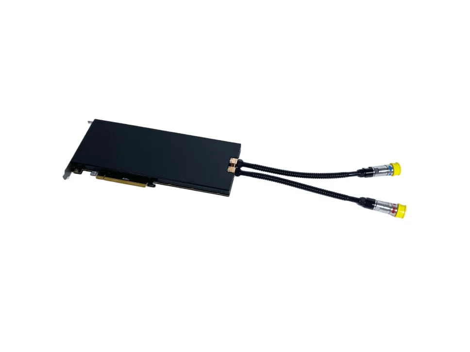
Identify every heat source the module must contact. If CPU and GPU devices share a loop, review the combined heat load, flow distribution and system controls.
| Route | Essential design input | Typical contact scope | Validation emphasis |
|---|---|---|---|
| CPU module | Socket, heat-spreader or die interface, mounting and nearby clearances | Concentrated processor heat source | Mounting load, contact and board/chassis fit |
| GPU module | Exact PCB revision and component-height map | GPU core plus agreed memory and power devices | Multi-height contact and complete board assembly |
| Combined system | All devices, loop and chassis configuration | Multiple CPU/GPU/other sources | Branch balance, temperature rise and system controls |
Contact pressure, interface material and flatness must suit the processor or board assembly. Confirm the exact hardware revision because a similar-looking board can have different mounting points or component heights.
The flow path must fit the heat-source distribution and the system the module enters. Review hydraulics, tube routing and service access as one integration decision.
Compare series, parallel or combined paths using the project pressure-drop budget and pump operating point.
CPU projects focus on board and memory clearances; GPU projects add card support, slot density and adjacent-board routing.
Define assembly order, connector access, leak-impact zones and what happens when a board or processor revision changes.
Both routes need controlled fit, sealing, flow and project-condition thermal evidence. GPU modules add multi-device contact and complete-card assembly checks; combined configurations also require system-level flow and control verification.
| Evidence | Common | CPU-specific review | GPU-specific review |
|---|---|---|---|
| Fit | Controlled drawing and assembly | Socket/mounting load | PCB revision, component contact and card structure |
| Fluid | Defined leak/pressure and flow condition | Module and chassis boundary | Branching and multi-device coverage |
| Thermal | Named workload, environment and controls | Processor/contact behavior | Core, memory and power-device evidence |
| Change | Impact assessment before release | Socket/CPU/mounting revision | PCB/component/backplate revision |
Send the exact platform revision, heat loads, mounting space, coolant connections, test requirements and expected quantity. Ask each supplier to identify included work and changes that would require further testing.
Yes, when the supplier can control the different thermal, contact, mounting, PCB and validation inputs. The development method can be shared, but the platform files and acceptance evidence cannot be assumed interchangeable.
A PCB revision can change component positions, heights, keep-out zones, mounting features and power distribution. Those changes can affect contact, interference, load and validation, so the controlled revision must be identified.
They can share a loop when the heat loads, coolant, flow distribution, pressure-drop budget, temperature rise, controls and failure response are designed for the complete configuration.
Changes to the processor or PCB revision, mounting, contact stack, coolant, module geometry, flow path, pump or radiator boundary, firmware or control, and chassis installation should be reviewed for revalidation impact.
Product examples: ThermalBro CPU and GPU liquid cooling modules. Confirm compatibility and cooling performance for the exact hardware and operating conditions.
Share the processor or PCB revision, heat sources, workload and chassis space. We will review the design requirements and suitable next steps.