
Motors and drives
Sustained torque, rapid motion and compact joints can build heat near bearings, windings and power electronics.
We develop compact cold plates and liquid cooling modules for robotic equipment. The design accounts for heat load, movement, weight and hose routing, with the supplied cooling hardware and tests agreed for each application.
Discuss a Robot Cooling Project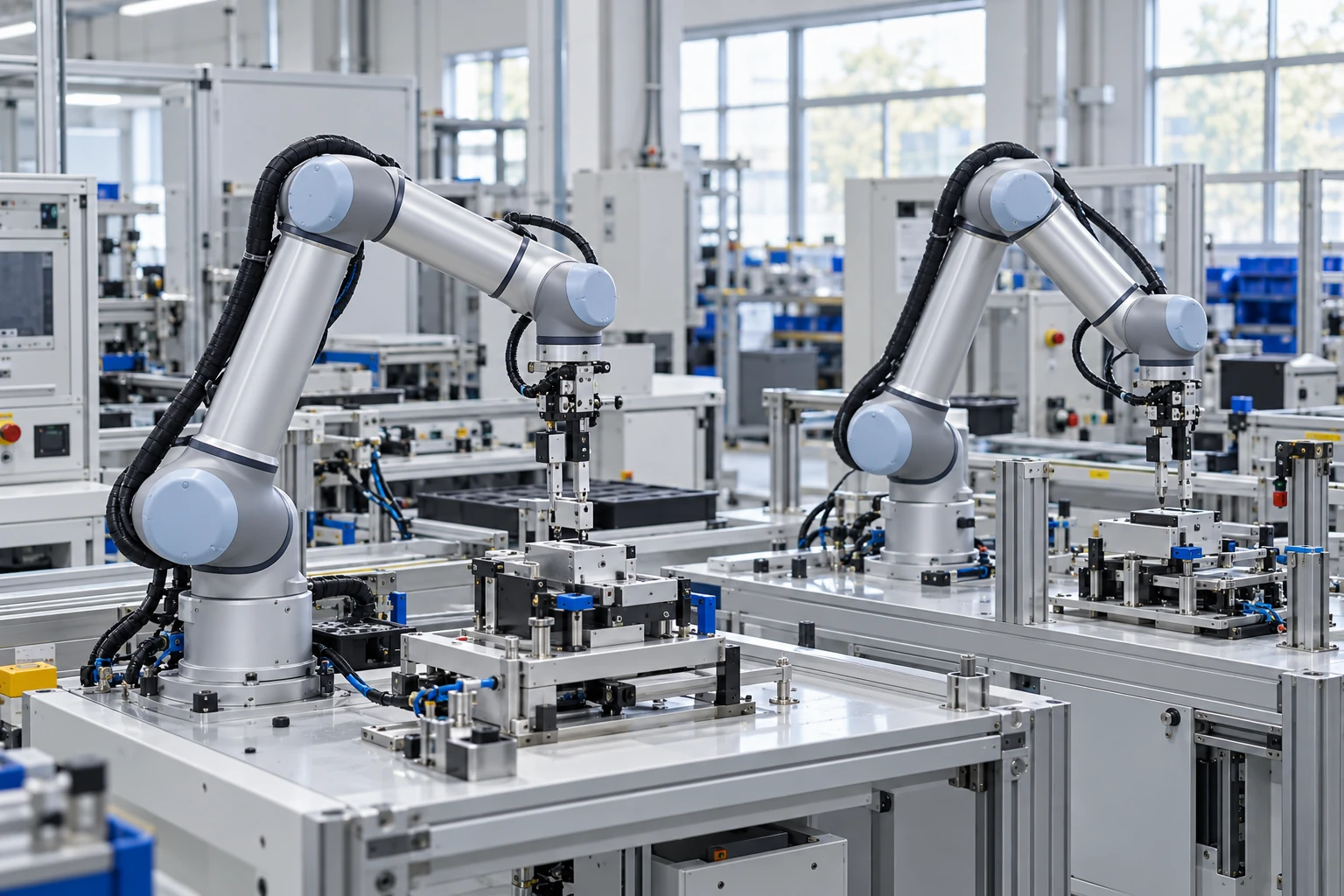
We assess the heat generated during the robot’s actual operating cycle. Motor load, controller use, movement and ambient conditions help determine where cooling is needed.
Sustained torque, rapid motion and compact joints can build heat near bearings, windings and power electronics.
Drives, control hardware and onboard compute may be concentrated inside sealed or noise-sensitive enclosures.
AMR or mobile-platform loads change with drive, charging, ambient and duty cycle.
Welding, laser or inspection tools can create additional heat loads and require separate coolant connections.
Liquid cooling can help when heat needs to move away from compact or sealed areas. The robot must also accommodate the pump, coolant, tubing and required service access.
| Robot context | Passive or air may fit when | Liquid may be worth reviewing when | Added constraints |
|---|---|---|---|
| Industrial arm or cobot | Joint and drive heat can leave through structure or local airflow. | Sustained motion or sealed joints require remote heat transport. | Joint motion, hose torsion, inertia, abrasion and safe stop response. |
| AMR / mobile robot | Controller and battery have sufficient airflow and ambient margin. | Battery, power or compute heat is concentrated in a sealed platform. | Weight, energy, shock, orientation, charging and service access. |
| Humanoid / service robot | Distributed loads stay within passive or fan limits. | Compact actuators and compute need controlled remote heat rejection. | Mass distribution, motion envelope, noise and multi-position bleeding. |
| Controller enclosure | Filtered or forced air meets the contamination and noise goals. | Sealed or high-density electronics need heat moved outside the cabinet. | Fluid connections, condensation, monitoring and external heat rejection. |
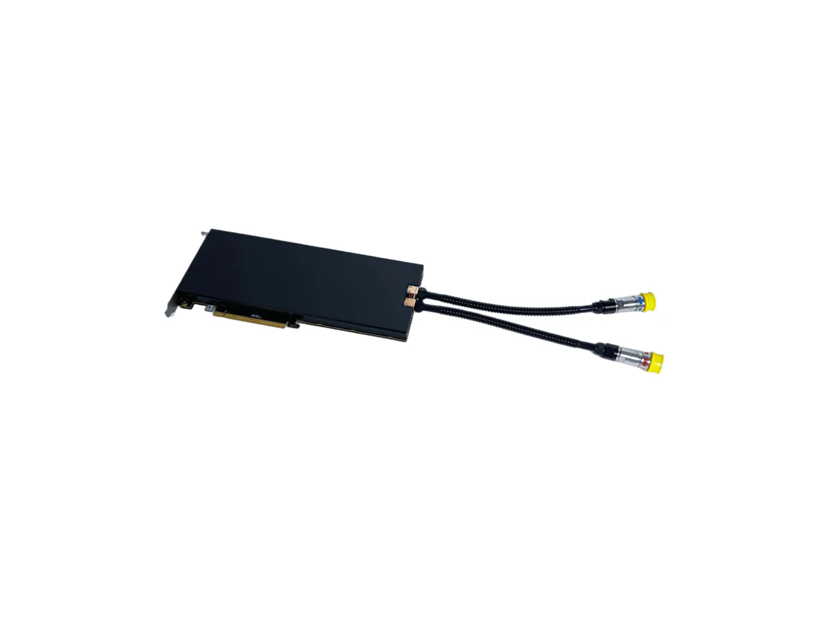
The liquid path has to survive the actual movement without violating the robot’s mass, envelope, service or connector limits.
We evaluate each subsystem against the available drawings and operating conditions. Cold-plate geometry, mounting and fluid connections are developed for the specific equipment rather than a universal robot fit.
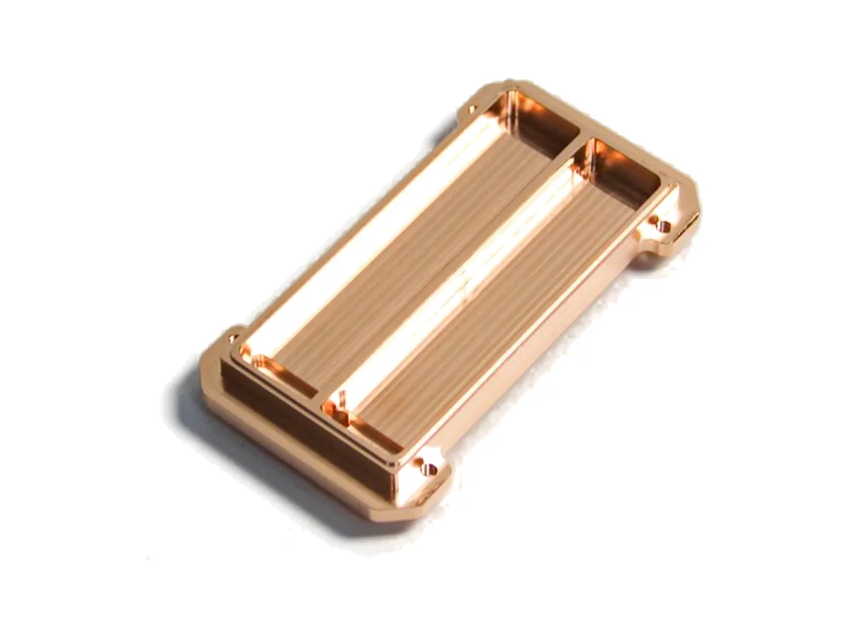
Match the contact surface and mounting to the heat source, with fluid connections clear of the moving structure.
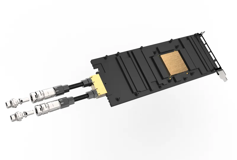
Develop cooling around the specified board, enclosure and contact areas, while preserving tube routing and remaining airflow.

Assess the device contact, electrical separation, fluid path and operating conditions before selecting the cooling arrangement.
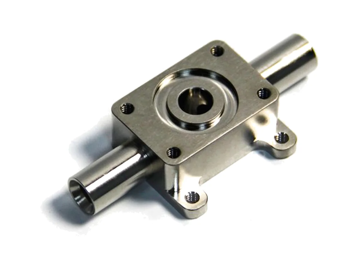
Coordinate process heat removal with the tool’s weight, connections, motion and service requirements.
Temperature, flow or leak signals can support system monitoring where included in the design. Your robot team defines the warnings, performance reduction and safe-stop response.
| Risk | Possible signal | Cooling-component input | Robot control response |
|---|---|---|---|
| Loss of flow | Flow, pressure or temperature trend | Sensor or interface requirement included in the reviewed scope | Warning, derating and safe-stop logic |
| Leakage | Leak sensor or unexpected pressure condition | Leak routing, electrical separation and connection design | Isolation, service and recovery procedure |
| Condensation | Surface temperature, humidity or dew-point input | Surface limit, insulation or drainage requirement | Control logic and permitted operating conditions |
| Overtemperature | Device or coolant temperature | Measurement location and operating limits | Performance reduction, stop and fault retention |
We agree component-level checks for the cooling hardware. The robot team then tests routing and operation through the intended poses, loads, speeds and duty cycles.
| Question | Potential test | Required project condition | Responsible team |
|---|---|---|---|
| Is the fluid path sealed? | Leak, pressure or connector-retention check. | Pressure, coolant, duration, orientation and acceptance criteria. | ThermalBro for agreed component scope |
| Does it move heat and fluid? | Flow, pressure-drop and thermal test. | Load by mode, inlet temperature, flow, ambient and fixture. | Shared; robot OEM validates real system |
| Does routing survive movement? | Motion-cycle, flex, torsion, abrasion or retention test. | Joint path, speed, cycle, payload, support and service life target. | Robot OEM / integrator |
| Does the platform survive its environment? | Project-defined temperature, vibration, shock, contamination or noise checks. | Installation, operating mode, standard, method and pass criteria. | Finished-system owner |

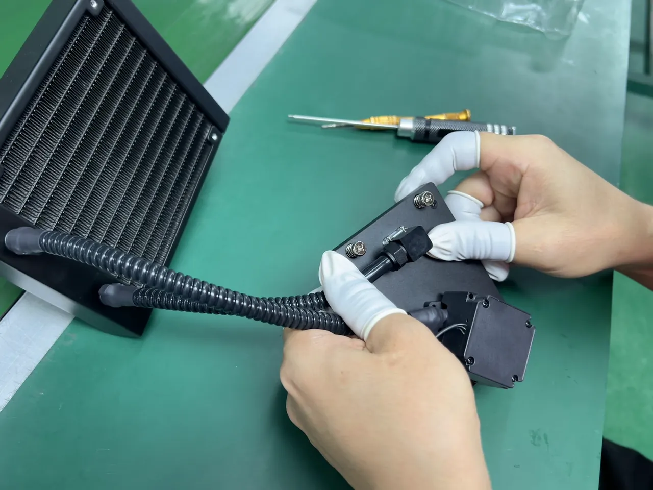
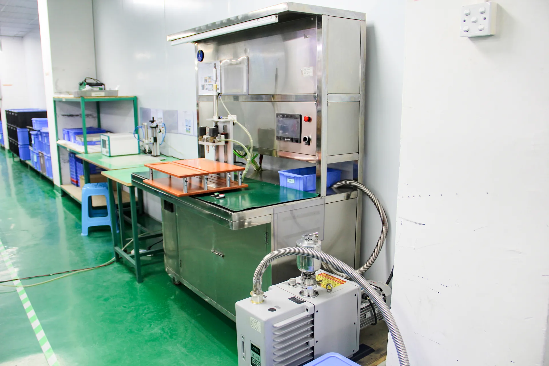
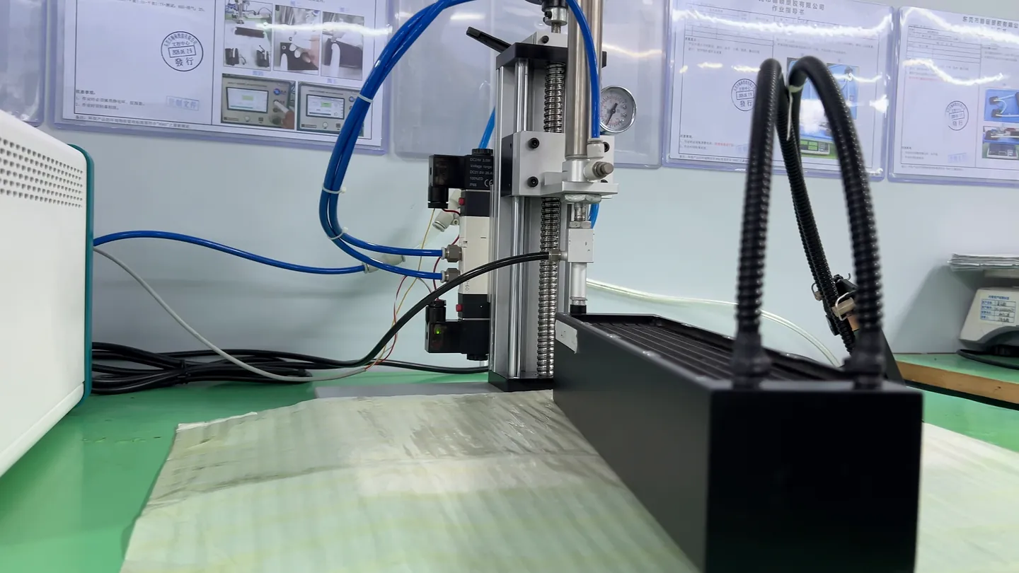
Answers about cooling arrangements, hose movement, monitoring and component testing.
Share the equipment layout, operating cycle and movement requirements. We will assess suitable cooling components and the information needed for a prototype.