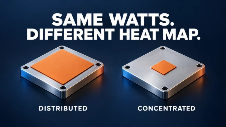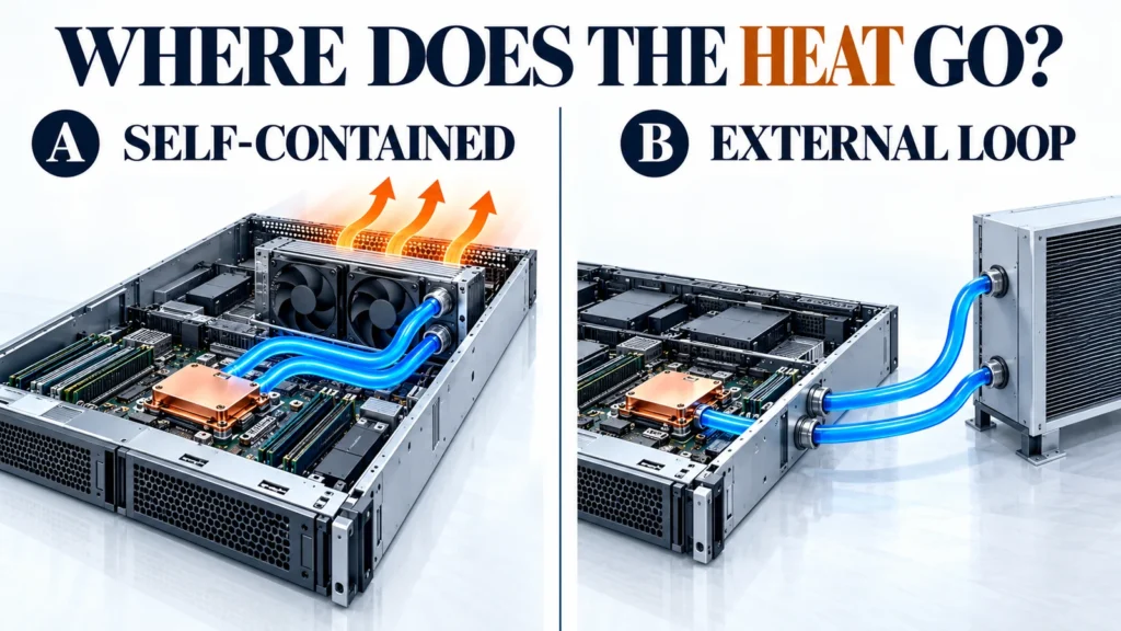
A server cooling proposal is incomplete if it tells you how heat leaves the processor but not where that heat goes next. A self-contained liquid-to-air module still sends its captured heat into the server's air path. An externally connected module passes that heat to equipment outside the node, which may reject it to room air or transfer it into a separate facility-water circuit.
The purchasing decision is therefore about a complete heat path and an agreed handover point. Before comparing module prices, identify who supplies the final heat-rejection equipment, who guarantees the conditions at the server connection, and who validates the installed system.
Define the boundary before choosing a cooling label
“Closed loop” and “external loop” are convenient buying terms, but they are not technical opposites. An external coolant distribution unit, or CDU, can also operate a closed secondary circuit. In this article, self-contained means a liquid-to-air module whose coolant circuit and radiator belong to the server assembly. Externally connected means the server has supply and return connections to separately supplied cooling equipment.
Direct-to-chip describes heat collection at a processor cold plate. It does not, by itself, tell you whether the final heat exchanger is inside the chassis, next to the rack, or connected to facility water. Vertiv's explanation of CDU arrangements distinguishes secondary coolant circuits from facility-water systems and describes both liquid-to-air and liquid-to-liquid heat rejection.
Use three questions on every proposal: Where does the coolant circuit cross the server boundary? Where does captured heat leave the cooling circuit? Who owns the conditions at each interface? Those answers are more useful than the word “liquid-cooled.”
Follow both the liquid heat path and the remaining air load
For a self-contained module, the main path is processor → thermal interface → cold plate → coolant → internal radiator → server exhaust air. The pump circulates coolant; it does not dispose of the heat. The chassis must provide radiator airflow, and the room cooling system must accept the resulting exhaust load.
For an externally connected module, the path continues from the cold plate through the node connections to rack distribution and an external heat exchanger. A liquid-to-liquid CDU transfers heat between separated circuits; facility water does not necessarily flow through the server cold plates. A liquid-to-air CDU instead rejects heat to the room. Vertiv's CoolChip CDU brochure, pages 2 and 4 illustrates these alternatives. This is an infrastructure example, not a statement that ThermalBro supplies that equipment.
Where the heat goes
Processor → cold plate → coolant
↓ Internal radiator → server exhaust → room cooling
Processor → node supply/return → rack distribution
↓ External air heat exchanger → room cooling
Processor → node supply/return → rack distribution
↓ CDU heat exchanger → separate facility-water circuit → site heat rejection
Cold plates do not automatically collect heat from every component. Memory, voltage regulators, storage, network devices and power supplies may still require airflow, depending on the design. List the components assigned to liquid cooling and the components left on air; do not use a generic percentage to estimate the split. The rack and site teams need both loads, including relevant auxiliary losses, when assessing their cooling duty.

Our server liquid cooling guide introduces the overall integration layers. The decision here is narrower: where your proposed module hands over its heat load and operating responsibility.
Compare the interfaces that change the project
Swipe the table horizontally to compare all columns.
| Decision | Self-contained liquid-to-air module | Externally connected module |
|---|---|---|
| Heat-rejection boundary | Module radiator transfers heat to chassis air; the server and room must handle the exhaust. | External equipment receives the liquid-carried load; identify whether it ultimately transfers heat to air or another liquid circuit. |
| Conditions needed for a quote | Radiator inlet-air range, available airflow and pressure resistance, fan limits, chassis layout and workload. | Coolant identity, node supply-temperature range, available flow and differential pressure, connection details and external equipment owner. |
| Mechanical integration | Radiator thickness, fan space, hose bends, neighboring components and exhaust path. | Coupling position, mating hardware, hose movement, manifold access and node removal sequence. |
| Control responsibility | Assign pump/fan power, feedback, startup behavior and server response to a cooling fault. | Add external-system readiness, node flow verification, alarms and isolation coordination. |
| Service boundary | Define whether the replaceable item is a complete sealed module or an approved serviceable assembly. | Define isolation, disconnection, residual-fluid handling, reconnection and restart responsibilities. |
| Acceptance | Module evidence plus a test in the actual chassis and airflow configuration. | Module evidence plus installed-node tests with the agreed external hydraulic and thermal conditions. |
An external connection adds an interface even if the module itself has fewer parts. Conversely, moving the radiator inside the server does not eliminate the room-side heat-rejection requirement. Compare quotations at the same boundary: a module-only price and a complete rack cooling price do not describe equivalent deliveries.
Capacity figures also need a common operating basis. A radiator result at one inlet-air temperature and fan setting is not directly comparable with a cold-plate result at a different coolant temperature and flow. Ask each supplier to state its measurement boundary, inlet condition, fluid or airflow, control setting and allowable component temperature. Then check the proposed combination at the required simultaneous load and limiting site conditions. Matching two headline capacity numbers does not establish a compatible system.
Match the architecture to what the site can actually support
The site has no facility-water connection
A self-contained module may be worth evaluating when the chassis has a workable radiator location and the air path can meet the operating target. Confirm the air temperature at the radiator inlet under the actual rack arrangement, not just a nominal room setpoint. Air that has already passed through hot components can create a different condition.
An external liquid-to-air CDU is another possible route. It can remove the need for a radiator in each node, but the room still receives the heat and the external unit still needs space, power, airflow and service access. “No facility water” is not enough information to approve either arrangement. Ask the server and site teams to assess the complete layout before selecting one.
The rack already provides supply and return connections
Existing connections are a starting point, not an acceptance certificate. Request the coolant specification, permitted operating range, coupling standard and pressure information at the node boundary. A pump's maximum flow does not establish the flow through your node after hoses, couplings, manifolds and other branches add resistance.
Ask for the node's pressure-drop requirement at the intended flow and fluid condition, and for the distribution system's available differential pressure at that same boundary. Keep this separate from maximum working pressure and proof-test pressure. Also identify how flow is allocated as nodes are added, isolated or placed under different loads. These inputs let the module supplier and infrastructure supplier evaluate the same operating point.
The site infrastructure is still being designed
Keep the proposal conditional where essential inputs are unavailable. A useful early output is a boundary drawing with open fields, named owners and dates for closing them. Do not turn an assumed coolant temperature into a guaranteed supply condition or release connection hardware before the mating interface is agreed.
The next prototype can still answer bounded questions—such as mechanical fit or a defined laboratory thermal condition—provided those results are not presented as proof of future site operation.
Write the handover conditions into the RFQ
A responsibility table should identify deliverables, not just label entire areas “shared.” The following is a proposed division to agree for your project, not a universal contract allocation.
Swipe the table horizontally to compare all columns.
| Handover item | Information to record | Owner to name |
|---|---|---|
| Heat sources and load | Hardware revision, sustained and peak load, simultaneous devices, allowed temperatures and measurement points. | Server OEM or platform owner. |
| Cooling interfaces | Node envelope, mounting, hose route, mating connectors, fluid direction and service movement. | Server integrator and module supplier, with one interface-release owner. |
| Node inlet condition | Coolant, concentration where applicable, temperature range, required flow and pressure-drop characteristic. | Module supplier defines requirements; external-loop owner confirms availability. |
| Pressure and materials | Working/transient pressure limits, wetted materials, seals, cleanliness and fluid compatibility evidence. | Suppliers responsible for the affected parts, coordinated by the system owner. |
| Air-side load | Radiator inlet/exhaust conditions and cooling of devices outside the liquid path. | Server thermal team and site cooling team at their respective boundaries. |
| Controls and faults | Readiness signal, measured condition, alarm threshold, permitted response time and shutdown/isolation action. | Named controls owner for the server and external system. |
| Service and release | Replaceable unit, isolation sequence, inspection after reconnection, restart checks and acceptance record. | Service owner and system release authority. |
For temperature control, include startup and abnormal conditions as well as steady operation. If coolant or exposed surfaces can fall below the surrounding air's dew point, the system needs an agreed condensation-control strategy. Do not insert a universal temperature margin without the applicable environment and control requirements. A CDU feature is not proof that every exposed node component is protected under every operating state.
For a factory-sealed module, specify whether opening the loop is prohibited in field service. For a disconnectable node, establish the permitted fluid-handling procedure and how the system confirms flow after reconnection. “Quick disconnect” does not make those checks unnecessary.
Separate module acceptance from installed-system acceptance
At module level, identify the sample, drawing revision, assembly state and the checks included in the supply scope. Leak, pressure and thermal tests answer different questions. Each needs its own conditions and pass criteria; one successful leak check cannot establish service life or thermal performance.
At installed-server level, run the agreed workload with the actual chassis, fan and pump controls, residual airflow and inlet conditions. At rack/site level, assess the interfaces controlled outside the node: distribution, cooling readiness, monitoring and the agreed response when a node or shared cooling component is unavailable. Failure-response exercises require an approved procedure and safe system state; do not improvise a loss-of-cooling test on production equipment.
Consider a hypothetical buyer who receives a passed module test at one coolant inlet temperature, but whose rack supplier has not yet committed to a supply-temperature range. The module result is useful evidence at the tested condition. It does not close the rack integration decision. The next action is to agree the external range and determine whether the existing evidence covers it or another test is needed. A second module quote alone does not resolve that missing interface.
The acceptance record should therefore say what was tested, which operating boundaries were represented, what remains open, and who can approve release. ThermalBro's testing and reliability scope follows this distinction between defined module checks and customer-system validation.
What to send for a ThermalBro module review
Send the server and board revision, heat-source layout, workload, chassis files and available air-side or liquid-side conditions. Identify the hardware you expect us to supply, the external equipment supplied by others, and the tests needed before your next project decision. A marked-up boundary drawing is useful even when some fields are still unresolved.
ThermalBro's server liquid cooling modules and related engineering are the relevant supply scope. Rack manifolds, CDUs, facility-water equipment and site controls require separately identified owners unless a specific written project scope says otherwise. For the wider cold-plate mechanism, use our direct-to-chip guide.
Questions buyers ask about cooling boundaries
Does an external loop always require facility water?
No. External equipment may reject heat to air instead. Confirm the actual heat exchanger and final heat destination; the presence of node supply and return hoses does not answer that question.
Can an existing closed-loop module simply be connected to a CDU?
Do not assume that conversion is supported. A factory-filled module may have its own pump, coolant, pressure limits and service restrictions. Its supplier and the external-system designer must review the altered circuit, materials, controls and validation scope before any modification.
Who is responsible if the processor exceeds its temperature limit?
The evidence must locate the deviation before responsibility can be assigned. Check the tested hardware, load, contact and mounting, flow, inlet temperature, controls and heat-rejection conditions against the agreed boundaries. The supply contract and interface record should identify which party owns each condition and the joint investigation process.